
Modular valve prosthesis with anchor stent and valve component

a module-type, heart valve technology, applied in the field of prosthetic heart valves, prosthetic heart valves, valves and methods for intraluminally deploying, etc., can solve the problems of restricted blood flow, insufficiency of blood leakage backward across the valve, and the proper functioning of the valv

Active Publication Date: 2015-04-30
MEDTRONIC INC
View PDF13 Cites 36 Cited by
  • Summary
  • Abstract
  • Description
  • Claims
  • Application Information

AI Technical Summary

Benefits of technology

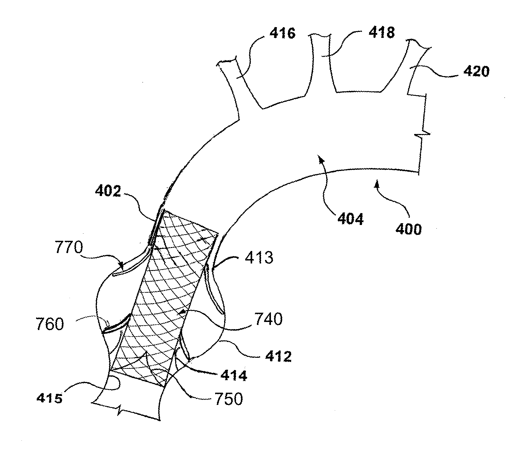
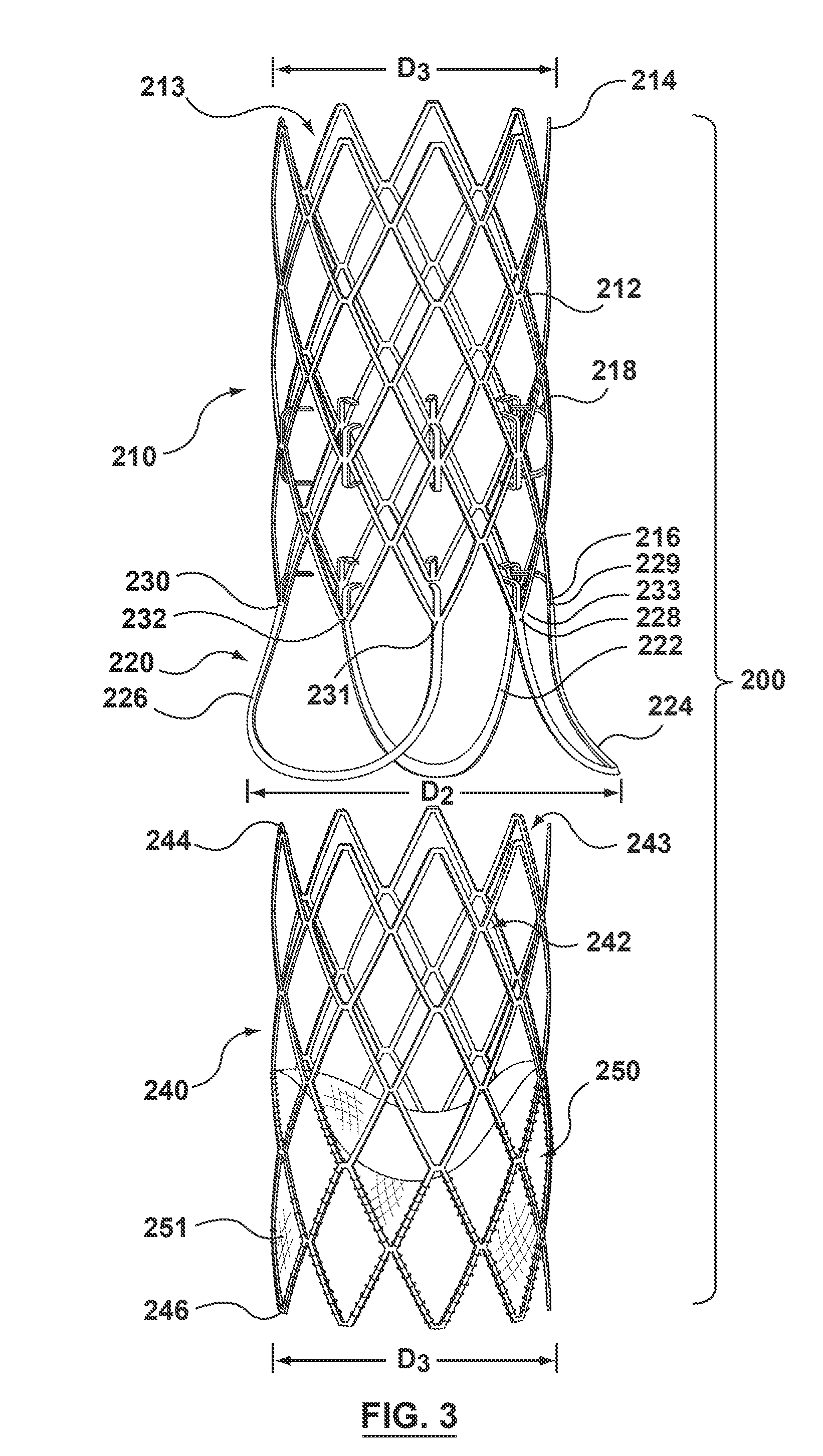
The patent text describes a modular valve prosthesis that includes an anchor stent and a valve component. The anchor stent is used to secure the valve prosthesis in place within the aorta and the sinuses of the aortic valve. The valve component is placed within the anchor stent and includes a valve frame and a prosthetic valve to restore the functionality of the native aortic valve. The modular design of this valve prosthesis allows for easy implantation and flexibility in placement within the body.

Problems solved by technology

Heart valves, such as the mitral, tricuspid, aortic, and pulmonary valves, are sometimes damaged by disease or by aging, resulting in problems with the proper functioning of the valve.
Heart valve problems generally take one of two forms: stenosis in which a valve does not open completely or the opening is too small, resulting in restricted blood flow; or insufficiency in which blood leaks backward across a valve when it should be closed.
Traditional open surgery inflicts significant patient trauma and discomfort, requires extensive recuperation times, and may result in life-threatening complications.
While considerable effort has been devoted to such techniques, widespread acceptance has been limited by the clinician's ability to access only certain regions of the heart using laparoscopic instruments.
Such a device may not be able to be crimped to a desired small diameter to navigate some tortuous or diseased vessels.
Further, it may be difficult to adjust the location of such a device during delivery to the desired location.

Method used


Image

  • Modular valve prosthesis with anchor stent and valve component
  • Modular valve prosthesis with anchor stent and valve component
  • Modular valve prosthesis with anchor stent and valve component

Examples


Embodiment Construction

[0023]Specific embodiments of the present invention are now described with reference to the figures, wherein like reference numbers indicate identical or functionally similar elements. The terms “distal” and “proximal” when used in the following description to refer to a catheter or delivery system are with respect to a position or direction relative to the treating clinician. Thus, “distal” and “distally” refer to positions distant from or in a direction away from the clinician and “proximal” and “proximally” refer to positions near or in a direction toward the clinician. When the terms “distal” and “proximal” are used in the following description to refer to a device to be implanted into a vessel, such as an anchor stent or valve component, they are used with reference to the direction of blood flow from the heart. Thus, “distal” and “distally” refer to positions distant from, or a direction away from the heart and “proximal” and “proximally” refer to positions near to, or a direc...


PUM


Abstract

A modular valve prosthesis includes an anchor stent and a valve component. The anchor stent includes a self-expanding tubular frame member configured to be deployed in the aorta and a proximal arm component extending from a proximal end of the tubular frame member and configured to be deployed in the sinuses of the aortic valve. The anchor stent further includes attachment members extending from an internal surface of the tubular frame member. The valve component includes a valve frame configured to be deployed within the tubular frame member of the anchor stent such that the valve frame engages with the attachment members of the tubular frame member and a prosthetic valve coupled to the valve frame.

Description

FIELD OF THE INVENTION[0001]Embodiments hereof relate to prosthetic heart, valves and methods for intraluminally deploying, prosthetic heart valves, and in particular, to a modular prosthetic heart valve including an anchor stent and methods of intraluminally deploying the anchor stent and the prosthetic heart valve.BACKGROUND OF THE INVENTION[0002]Heart valves, such as the mitral, tricuspid, aortic, and pulmonary valves, are sometimes damaged by disease or by aging, resulting in problems with the proper functioning of the valve. Heart valve problems generally take one of two forms: stenosis in which a valve does not open completely or the opening is too small, resulting in restricted blood flow; or insufficiency in which blood leaks backward across a valve when it should be closed.[0003]Heart valve replacement has become a routine surgical procedure for patients suffering from valve regurgitation or stenotic calcification of the leaflets. Conventionally, the vast majority of valve ...

Claims


Application Information

Patent Timeline
IPC IPC(8): A61F2/24A61F2/852
CPCA61F2/2418A61F2002/826A61F2/852A61F2220/0008A61F2220/0025A61F2250/006
Inventor ROTHSTEIN, PAUL
Owner MEDTRONIC INC
Learn More