Refueling detection method

a detection method and fuel tank technology, applied in the direction of machines/engines, electrical control, instruments, etc., can solve the problem of few opportunities to purge fuel tank vapors to the engine, and achieve the effects of reducing vehicle emissions, reducing pressure out of the fuel tank, and high fidelity

Active Publication Date: 2015-05-07
FORD GLOBAL TECH LLC
View PDF5 Cites 21 Cited by
  • Summary
  • Abstract
  • Description
  • Claims
  • Application Information

AI Technical Summary

Benefits of technology

[0004]In this way, output from the hydrocarbon sensor may be used to detect a fuel event. In one example, the fuel event may include a fuel tank refill event where fuel is pumped to the fuel tank from an external fuel source. During such conditions, fuel vapors present in the fuel tank, as well as fuel vapors introduced during the fuel tank refill, may be displaced by the fuel volume to the fuel vapor canister. These displaced fuel vapors may pass by the hydrocarbon sensor prior to reaching the canister. If the hydrocarbon sensor senses a sudden increase the concentration of hydrocarbons in the vapor flow, it may indicate a fuel tank refill event is occurring. As such, if an engine-off leak detection test is being performed or is about to be performed, it may be aborted to prevent false positive or false negative readings caused by the pressure disturbance of the fuel tank refill.
[0005]In another example, the fuel event may include completion of a depressurization of the fuel tank preceding a refueling event. As explained above, the engine in a hybrid vehicle may be operated infrequently, leading to few opportunities to purge fuel tank vapors to the engine. As a result, the fuel tanks of the hybrid vehicles may be configured to store fuel vapors at relatively high pressure. Therefore, hybrid vehicle fuel systems may include locking fuel doors that are opened only after the fuel tank has been depressurized, to prevent leakage of fuel vapors and mist to the atmosphere. Accordingly, following an indication from an operator of the vehicle that a refueling event is about to occur, the fuel tank isolation valve or other fuel tank venting valve may be opened to relieve the pressure out of the fuel tank. The fuel vapors in the tank may be routed to the canister, past the hydrocarbon sensor. Thus, if the hydrocarbon sensor senses an increase in hydrocarbon concentration subsequent to the refueling request and / or the opening of the fuel tank isolation valve, followed by a leveling off of the hydrocarbon concentration, it may indicate that the depressurization of the fuel tank is complete, and the fuel door may be unlocked to allow the refueling to begin.
[0006]Thus, the hydrocarbon sensor present in the hybrid vehicle fuel system may be advantageously used to determine whether the fuel tank is being refilled or whether a depressurization of the fuel tank is complete. In doing so, diagnostic leak routines may be performed with high fidelity and / or vehicle emissions may be reduced by reducing the likelihood fuel vapors will leak to atmosphere during a refueling event. Further, the hydrocarbon sensor may act as a back-up sensor to other fuel tank sensors that have previously been used to detect fuel tank events (such as a fuel tank pressure sensor). As such, if the other sensors degrade, the fuel tank events may continue to be detected via the hydrocarbon sensor. Additionally, output from the hydrocarbon sensor may be used during the fuel tank event as a rationality check to ensure the fuel system valves and sensor are functioning as intended.

Problems solved by technology

As such, if an engine-off leak detection test is being performed or is about to be performed, it may be aborted to prevent false positive or false negative readings caused by the pressure disturbance of the fuel tank refill.
As explained above, the engine in a hybrid vehicle may be operated infrequently, leading to few opportunities to purge fuel tank vapors to the engine.

Method used


Image

  • Refueling detection method
  • Refueling detection method
  • Refueling detection method

Examples


Embodiment Construction

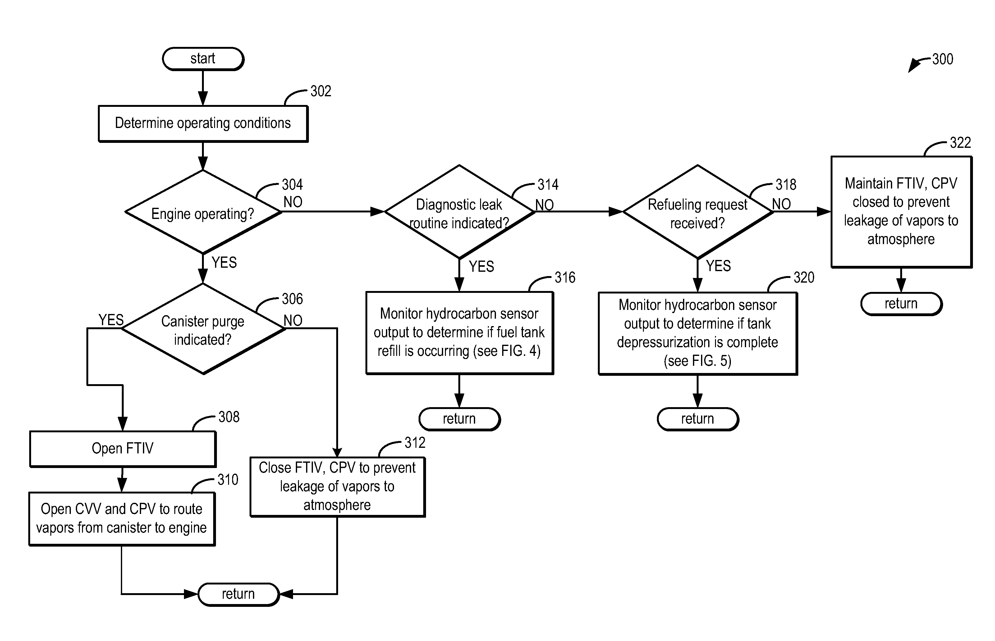
[0013]Evaporative emission (EVAP) system diagnostic leak detection tests that monitor fuel system pressure and / or vacuum have been used. EVAP diagnostic leak detection tests may be conducted during engine-off conditions because fuel system pressure disturbances, such as fuel slosh, arising from regular vehicle operation may be absent. A typical diagnostic leak detection test may seal the EVAP system by closing the canister vent valve (CVV) and then monitor changes in fuel system vacuum and / or pressure to determine system integrity when the engine is off. However, if refueling is started during an engine-off diagnostic leak detection test, the ensuing increase in fuel system pressure due to the dispensed fuel may confound the results of the diagnostic leak detection test. Furthermore, the buildup in fuel system pressure may prematurely shutoff the fuel dispensing pump.

[0014]Additionally, during refueling of a fuel tank, a fuel door may be maintained locked until sufficient depressuri...


PUM


Abstract

Embodiments for detecting fuel events are presented. In an embodiment, a method comprises performing an action responsive to a fuel event indicated based on output from a hydrocarbon sensor positioned between a fuel tank and a fuel vapor canister. In this way, the hydrocarbon sensor may be used to detect fuel events and engine operation may be adjusted accordingly.

Description

FIELD[0001]The present disclosure relates to systems and methods for operation of on-board fuel vapor recovery systems.BACKGROUND AND SUMMARY[0002]Hybrid vehicle fuel systems may include a sealed fuel tank configured to withstand high fuel tank pressure and vacuum levels. Fuel tank pressure or vacuum levels may build up due to engine operating conditions as well as the generation of diurnal vapors over vehicle drive cycles. These hybrid vehicle fuel systems may include a fuel tank isolation valve or other similar valves to seal the fuel tank off from the atmosphere and ensure fuel vapors do not leak. However, during refueling or when the pressure inside the fuel tank reaches the capacity of the fuel tank, the fuel tank vapors may be released into and stored in a fuel vapor canister packed with an adsorbent by opening the fuel tank isolation valve, coupled between the fuel tank and the canister. At a later time, such as when the engine is in operation, the stored vapors can be purged...

Claims


Application Information

Patent Timeline
Patent Type & Authority Applications(United States)
IPC IPC(8): F02D41/22F02M25/08
CPCF02D41/22Y10S903/904F02M25/089F02D41/221F02D41/0045F02D2041/225Y02T10/40
Inventor DUDAR, AED M.YANG, DENNIS SEUNG-MAN
Owner FORD GLOBAL TECH LLC
Why Eureka
Try Eureka