Display panel with varying conductive pattern zone

Active Publication Date: 2015-05-07
INNOLUX CORP
View PDF3 Cites 4 Cited by
  • Summary
  • Abstract
  • Description
  • Claims
  • Application Information

AI Technical Summary

Benefits of technology

[0008]The disclosure is directed to a display panel, such as an organic electroluminescence display panel, with a varying pattern zone. In the embodiment, the display panel comprises conductive patterns at the metal region and non-metal region, and the conductive patterns are corresponding to the sealant dispensing area. The conductive patterns at the metal region (ex: the conductive portions) and the non-met

Problems solved by technology

Since the organic materials and metal cathode of the OLED are highly sensitive to water vapor and oxygen, the device will be deteriorated soon after penetration of water vapor and oxygen.
Therefore, different properties between the metal regions and non-metal regions lead to considerable differences of thermal conductivities which may cause the problems of crack on the sealant an

Method used


Image

  • Display panel with varying conductive pattern zone
  • Display panel with varying conductive pattern zone
  • Display panel with varying conductive pattern zone

Examples


Example

First Embodiment

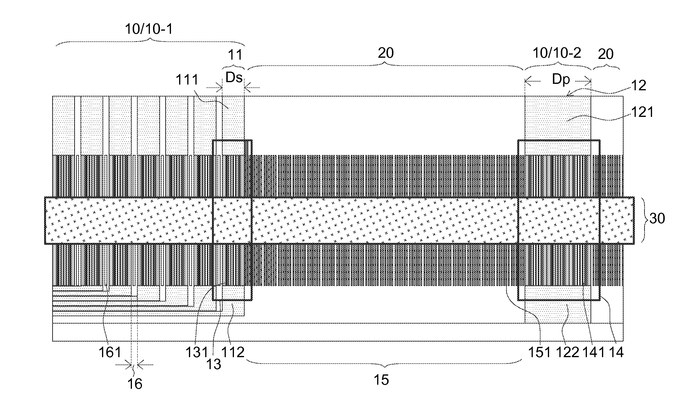
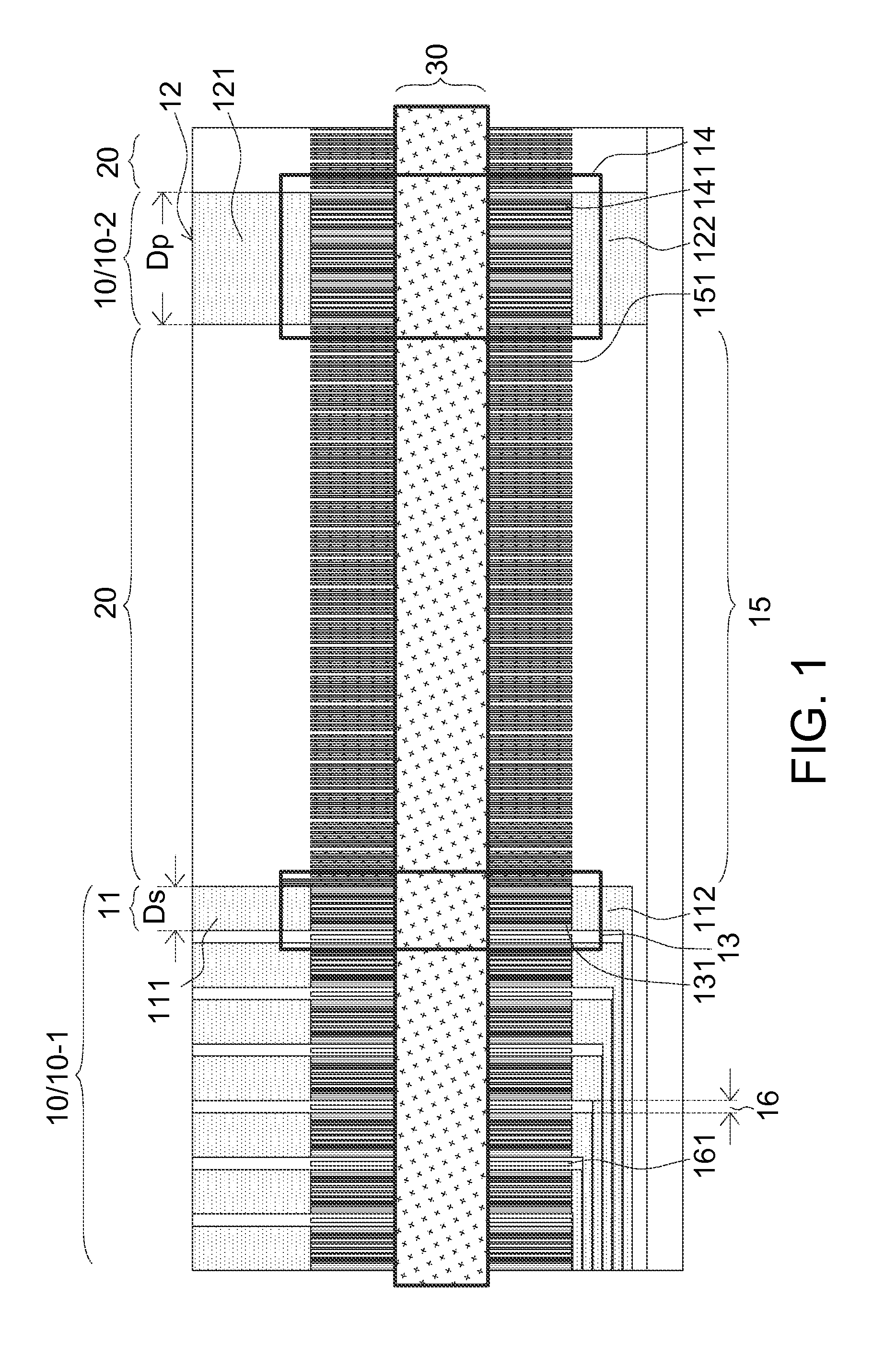
[0021]FIG. 1 illustrates a portion of a display panel according to the first embodiment of the present disclosure. A display panel comprises a first substrate, a second substrate disposed correspondingly to the first substrate, and a sealant positioned dispensed near the edges of the first substrate and the second substrate for gluing the first substrate and the second substrate. When the embodiment is applied to an OLED, the display panel further comprises an organic light-emitting layer positioned between the first substrate and the second substrate. The first substrate and the second substrate can be a CF substrate and a TFT substrate, respectively. In the embodiments described below, a TFT substrate is exemplified as the second substrate for illustration, but not for limitation. The first substrate and the second substrate can be a TFT substrate and a CF substrate, respectively. Also, the first substrate and the second substrate can be a TFT substrate and a frit ...

Example

Second Embodiment

[0049]Please refer to FIG. 1, FIG. 4 and FIG. 5. FIG. 4 illustrates a varying pattern zone at the metal region comprising a conductive net according to the second embodiment of the present disclosure. FIG. 5 illustrates a varying pattern zone at the metal region comprising another conductive net according to the second embodiment of the present disclosure. Position of the varying pattern zone of the second embodiment is corresponding to the sealant dispensing area 30, and the design of the varying pattern zone of the second embodiment can be applied to any metal trace (such as signal line 11 or the power line 12) at the metal region 10, and particularly suitable for the bigger area of the metal region. In the second embodiment, the varying pattern zone comprises a conductive net with a plurality of meshes, and the meshes are, not limitedly, arranged from dense to loose along the direction from the metal region 10 toward the non-metal region 20.

[0050]A varying patter...


PUM


Abstract

An organic electroluminescence display panel comprises a first substrate, a second substrate assembled to the first substrate, an organic light-emitting layer positioned between the first and second substrates, a sealant positioned between the first and second substrates, a varying pattern zone, and supplemental pattern zone. The second substrate comprises a sealant dispensing area, a metal region, and a non-metal region adjacent to the metal region. The metal region includes plural traces. The sealant is formed in the sealant dispensing area of the second substrate. The varying pattern zone is formed at one of the traces of the metal region, and is corresponding to the sealant dispensing area. The varying pattern zone comprises plural conductive portions. The supplemental pattern zone comprising plural supplemental conductive portions is formed at the non-metal region. A width of the conductive portions is larger than a width of the supplemental conductive portions.

Description

[0001]This application claims the benefit of Taiwan Application No. 102140115, filed Nov. 5, 2013, the subject matter of which is incorporated herein by reference.BACKGROUND[0002]1. Field of the Invention[0003]The disclosure relates in general to a display panel, and more particularly to a display panel with varying conductive pattern zone.[0004]2. Description of the Related Art[0005]Today, electronic products with displays panels, such as smart phones, tablet personal computers (i.e. tablet PC, flat PC, ex: iPad), laptops, monitors, and televisions, have become indispensable necessities for working-processing-learning or personal leisure entertaining in the daily life of the modern human beings. Penetration of water vapor / oxygen into the displays panels has considerable effect on the operation lifetime of the electronic device. It is known that the organic light emitting diode display (OLED) has the most severe requirement on the water vapor / oxygen blocking rate.[0006]Since the org...

Claims


Application Information

Patent Timeline
IPC IPC(8): H01L27/32H01L51/52
CPCH01L27/3276H01L27/3251H01L51/5246H10K50/8426H10K59/131H10K59/127
Inventor KAO, CHI-LUNHUANG, HAO-JUNGHSU, YI-HUA
Owner INNOLUX CORP
Why Eureka
Try Eureka