LED light fixtures with arrangement for electrical connection

a technology of led light fixtures and electrical connections, applied in the field of led light fixtures, can solve the problems of high-luminance light fixtures using leds as light sources, add risk of imperfections, and manufacture of modular fixtures, and achieves the effects of low manufacturing cost, excellent performance, and high product quality

Active Publication Date: 2015-05-07
IDEAL IND LIGHTING LLC
View PDF1 Cites 16 Cited by
  • Summary
  • Abstract
  • Description
  • Claims
  • Application Information

AI Technical Summary

Benefits of technology

[0006]The present invention relates to improved LED light fixtures which provide the advantages of low-cost manufacture with high product quality and excellent performance, by virtue of improvement in electrical connection to and between LED-array modules.
[0023]With this arrangement, such channel is spaced from the mounting structure on the light-emission side thereof. If the mounting structure is a heat sink, use of the exterior wireway structure facilitates thermal connections between the LED emitter(s) and the heat sink. Such structure may also lower manufacturing costs by simplifying assembly and in some cases saving material costs.

Problems solved by technology

High-luminance light fixtures using LEDs as light source present particularly challenging problems.
One particularly challenging problem for high-luminance LED light fixtures relates to achieving manufacturing efficiencies and ease of assembly while at the same time producing high quality sturdy light fixtures that fully comply with applicable standards, including UL and other regulatory standards.
However, manufacture of modular fixtures presents a challenge with respect to the electrical connection to and between LED-array modules.
In some prior LED light fixtures, assembly required alignment of wiring-related parts that was difficult to achieve and the failure of which would complicate assembly and add risk of imperfections in sealing arrangements intended to protect the LEDs—and thus extend the useful life of the LED lighting products.

Method used


Image

  • LED light fixtures with arrangement for electrical connection
  • LED light fixtures with arrangement for electrical connection
  • LED light fixtures with arrangement for electrical connection

Examples


Embodiment Construction

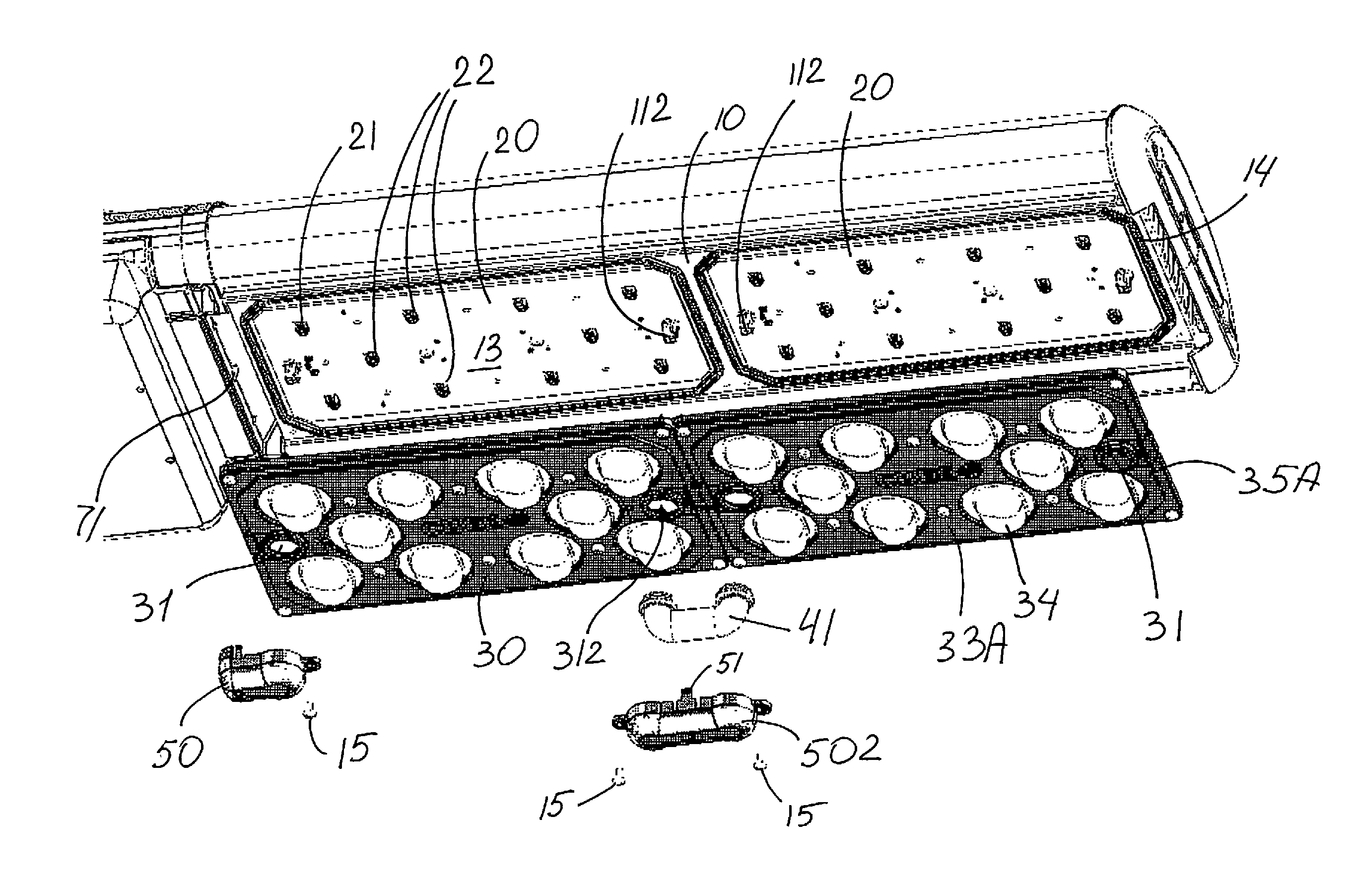
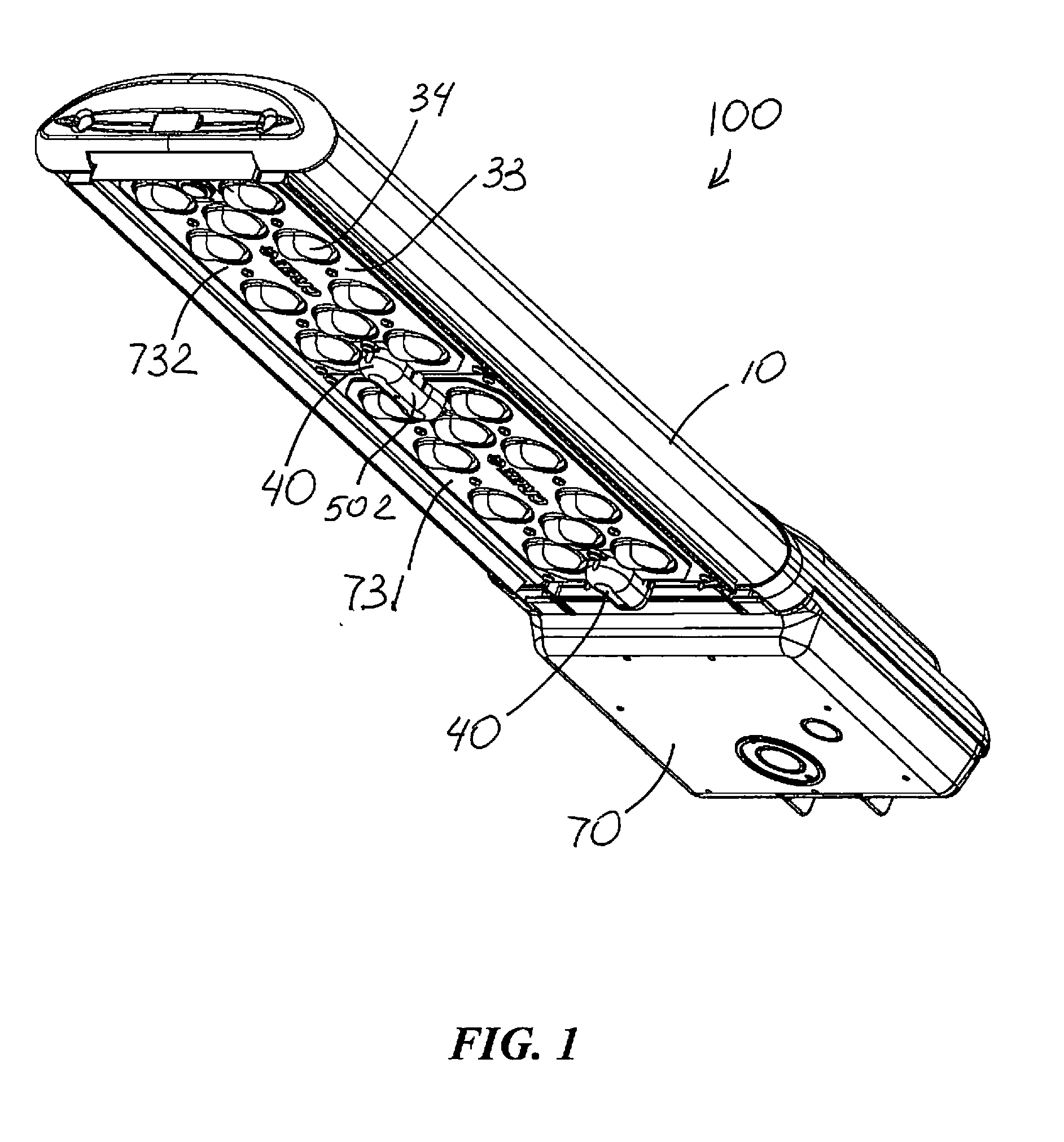
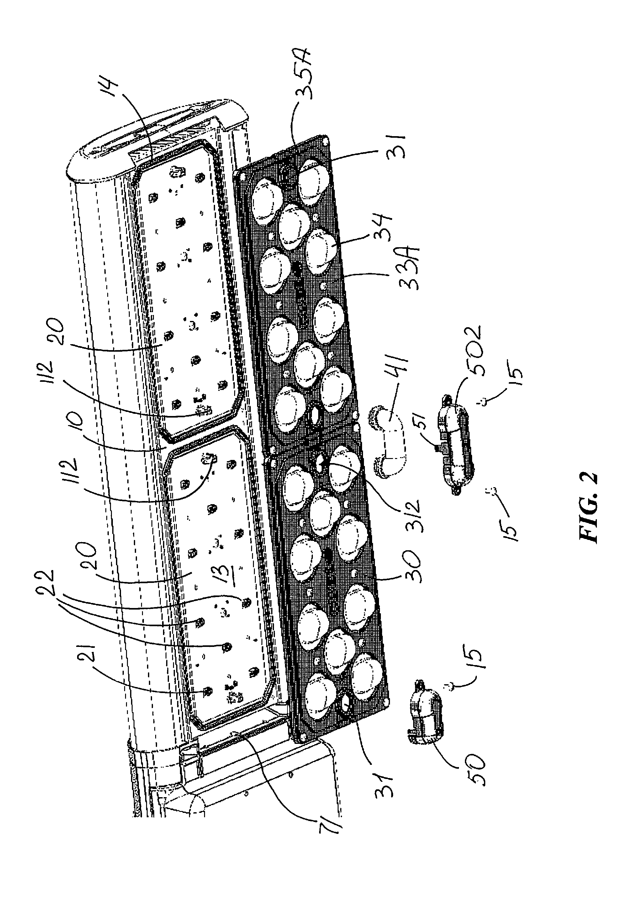
[0058]FIGS. 1-10 illustrate an exemplary embodiment of an improved LED light fixture100. As seen in FIGS. 1-3, LED light fixture 100 includes a heat sink structure 10 and at least one LED board 20 in thermal engagement with heat sink structure 10. LED board 20 is shown to have an LED emitter 21 with an array of LED light sources 22 spaced along board 20. FIG. 9 shows LED light source 22 including an array of LEDs 23. Alternative examples of LED light sources are shown in FIGS. 14-19 and described later in this section.

[0059]An on-board connector 11 is disposed on LED board 20 for connecting electrical wiring 12 to LED emitter 21. FIGS. 8 and 9 best show connectors 11 as vertical on-board connectors such as connectors manufactured by Molex Incorporated under its trademark MicroFit. As best seen in FIG. 8, connectors 11 include a female member 11A on LED board 20 and a male member 11B secured to wiring 12. Such connectors provide a desirable range of power distribution and are configu...


PUM


Abstract

An LED light fixture includes a heat sink structure, at least one LED board in thermal engagement with the heat sink structure, the at least one LED board having at least one LED emitter thereon, and an on-board connector on the LED board for connecting electrical wiring to the LED emitter(s). At least one enclosing member forms with the heat sink an interior space enclosing a corresponding LED board, the rigid enclosing member defining a wiring aperture therethrough in alignment with the on-board connector. The LED light fixture also has an exterior wireway structure including a one-piece duct which has an end portion engaged with the wiring aperture and forms a channel for wires to the on-board connector. The wireway structure further includes a single-piece rigid cover secured with respect to the enclosing member and enclosing the duct.

Description

FIELD OF THE INVENTION[0001]This invention relates to light fixtures and, more specifically, to light fixtures having LED emitters as light sources and, still more specifically, to arrangements for electrical connection.BACKGROUND OF THE INVENTION[0002]In recent years, the use of light-emitting diodes (LEDs) in development of light fixtures for various common lighting purposes has increased, and this trend has accelerated as advances have been made in the field. Indeed, lighting applications which previously had typically been served by fixtures using what are known as high-intensity discharge (HID) lamps are now being served by LED light fixtures. Such lighting applications include, among a good many others, roadway lighting, factory lighting, parking lot lighting, and commercial building lighting.[0003]High-luminance light fixtures using LEDs as light source present particularly challenging problems. One particularly challenging problem for high-luminance LED light fixtures relate...

Claims


Application Information

Patent Timeline
Patent Type & Authority Applications(United States)
IPC IPC(8): F21K99/00F21V5/04F21V29/00
CPCF21K9/50F21V5/04F21V29/22F21K9/60F21S8/086F21V29/767F21Y2105/10F21Y2115/10
Inventor WILCOX, KURTBENDTSEN, ANDREWQUELLA, DAN
Owner IDEAL IND LIGHTING LLC
Why Eureka
Try Eureka