Method of estimating diaphragm excursion of a loudspeaker

a loudspeaker and diaphragm technology, applied in the direction of transducer circuit damping, amplifier protection circuit arrangement, amplifier, etc., can solve the problems of temporary or permanent inoperative, mechanical damage, undue restriction of the maximum sound pressure of the loudspeaker, so as to improve the accuracy of the diaphragm excursion estimate and reduce the computational load

Active Publication Date: 2015-05-07
ANALOG DEVICES INT UNLTD
View PDF13 Cites 50 Cited by
  • Summary
  • Abstract
  • Description
  • Claims
  • Application Information

AI Technical Summary

Benefits of technology

[0017]The use of the predetermined non-linear function which represents the non-linear relationship between the loudspeaker parameter and the predetermined loudspeaker variable in the non-linear state-space model improves the accuracy of the diaphragm excursion estimate. Hence, the present methodology allows accurate control or limitation of the instantaneous diaphragm excursion circumventing the previously discussed problems associated with underestimating and overestimating the diaphragm excursion.
[0018]The skilled person will understand that the predetermined non-linear function may form an integral portion of the non-linear state-space model of the electrodynamic loudspeaker or the non-linear function may be computed in a separate pre-processing block or step before application to a linear state-space model of the

Problems solved by technology

If the maximum excursion limit is exceeded, various kinds to transitory or permanent mechanical damage may be imparted to the loudspeaker leaving the latter temporarily or permanently inoperative.
The mechanical damage may be caused by collision between movable loudspeaker components, such as the voice coil, diaphragm or voice coil bobbin, and a stationary component of the loudspeaker such as the magnetic circuit.
On the other hand, if the diaphragm excursion is overestimated and the excursion limitation therefore activated at an instantaneous excursion well below the maximum excursion limit of the loudspeaker in question, the maximum sound pre

Method used


Image

  • Method of estimating diaphragm excursion of a loudspeaker
  • Method of estimating diaphragm excursion of a loudspeaker
  • Method of estimating diaphragm excursion of a loudspeaker

Examples


Embodiment Construction

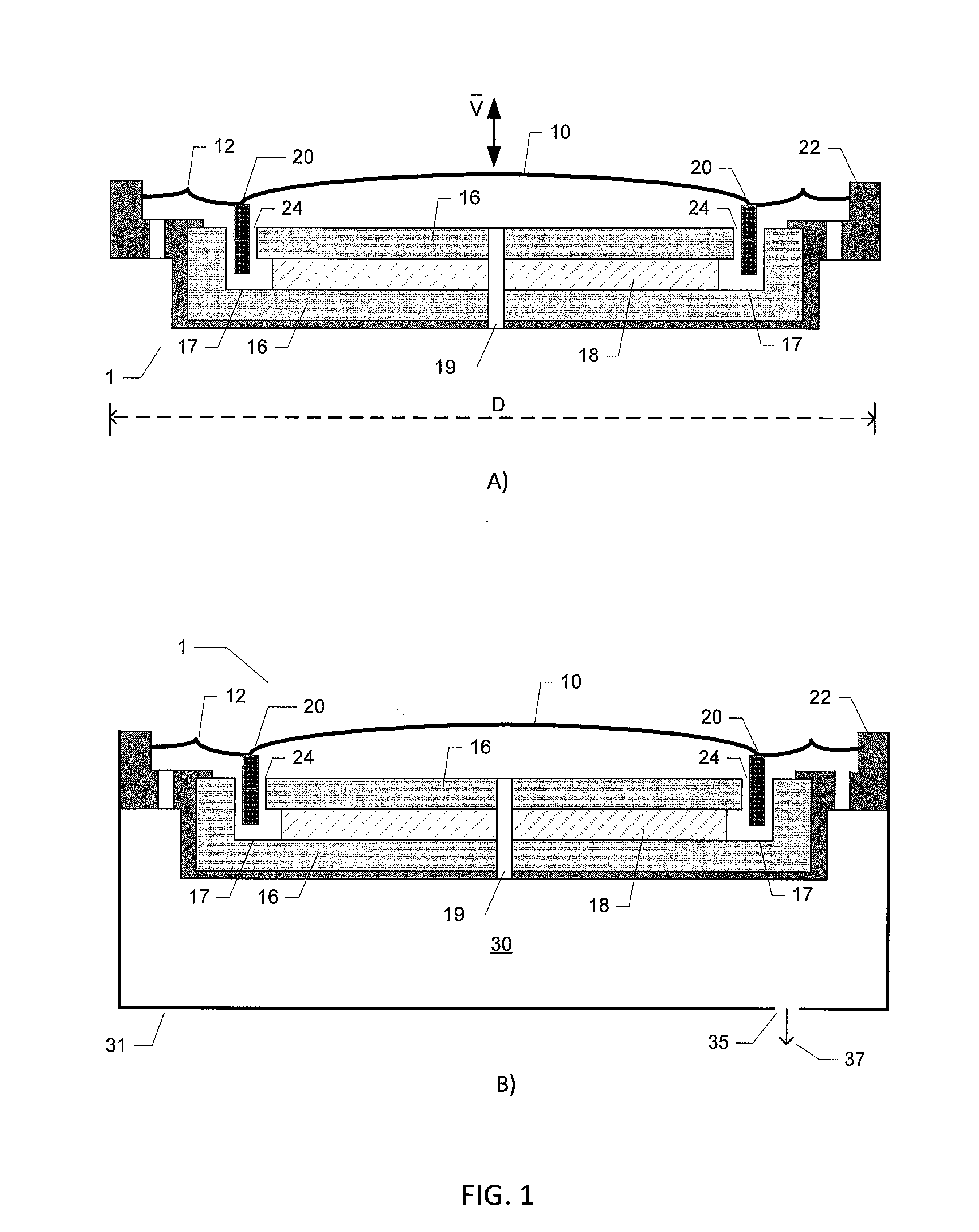
[0070]FIG. 1A) is a schematic cross-sectional illustration of a typical miniature electrodynamic loudspeaker 1 for sealed box mounting and use in portable audio applications such as mobile phones and smartphones where the loudspeaker 1 provides sound reproduction for various types of applications such as speaker phone and music playback. The skilled person will appreciate that electrodynamic loudspeakers exist in numerous shapes and sizes depending on the intended application. The electrodynamic loudspeaker 1 used in the below described methodologies of estimating diaphragm excursion and the corresponding assemblies for estimating diaphragm excursion has a rectangular shape with maximum outer dimension, D, of approximately 15 mm and an outer dimension in transversal direction of about 11 mm. However, the skilled person will appreciate that the present methodologies for estimating diaphragm excursion of electrodynamic loudspeakers are applicable to virtually all types of electrodynam...


PUM


Abstract

A method of estimating diaphragm excursion of an electrodynamic loudspeaker may be performed using audio signals. An audio output signal may be applied to a voice coil of the electrodynamic loudspeaker through an output amplifier to produce sound. A detected voice coil current and a determined voice coil voltage may be applied to a linear adaptive digital loudspeaker model that has a plurality of adaptive loudspeaker parameters. The parameter values of the adaptive loudspeaker parameters may be computed based on the linear adaptive digital loudspeaker model and applied to a non-linear state-space model of the electrodynamic loudspeaker. For the non-linear state-space model, a predetermined non-linear function may be applied to at least one of the plurality of received parameter values to compute at least one non-linearity compensated parameter value of the adaptive loudspeaker parameters, to determine an instantaneous excursion of the diaphragm.

Description

[0001]The present invention relates to a method of estimating diaphragm excursion of an electrodynamic loudspeaker comprising steps of receiving an audio input signal and generating an audio output signal based thereon. The method comprises steps of applying the audio output signal to a voice coil of the electrodynamic loudspeaker through an output amplifier to produce sound, applying a detected voice coil current and a determined voice coil voltage to a linear adaptive digital loudspeaker model comprising a plurality of adaptive loudspeaker parameters. The method comprises further steps of computing a plurality of parameter values of the plurality of respective adaptive loudspeaker parameters based on the linear adaptive digital loudspeaker model and applying the plurality of parameter values to a non-linear state-space model of the electrodynamic loudspeaker. A step of applying, in the non-linear state-space model, a predetermined non-linear function representing a non-linear rela...

Claims


Application Information

Patent Timeline
IPC IPC(8): H04R29/00
CPCH04R29/001H04R3/007H03F1/52H03F2200/462H03F2200/471H03G7/08H03G9/005H03G11/04H04R1/00H04R3/002H04R29/00H04R29/003
Inventor BERTHELSEN, KIM SPETZLERSTRANGE, KASPER
Owner ANALOG DEVICES INT UNLTD
Why Eureka
Try Eureka