Magnetic-Field Sensing Method

a magnetic field and sensing technology, applied in the field of magnetic field sensing method, can solve the problems of high manufacturing cost and down-scaled semiconductor elements, low process yield, more significant inaccuracy and poor sensing quality, etc., and achieve the effect of reducing manufacturing cost, low process yield and inaccuracy reduction

Inactive Publication Date: 2015-05-14
VOLTAFIELD TECH
View PDF0 Cites 58 Cited by
  • Summary
  • Abstract
  • Description
  • Claims
  • Application Information

AI Technical Summary

Benefits of technology

[0007]In one embodiment of the present invention, a planar magnetoresistive sensing device is used to sense two-dimensional magnetic-field components in parallel with the substrate plane to further estimate the three-dimensional magnetic field above the substrate plane. Since the magnetic-field component perpendicular to the substrate plane can be estimated without using additional multi-chip or three-dimensional structured magnetoresistive sensing devices, the magnetic-field sensing device in one embodiment of the present invention uses less complicated configurations to reduce the manufacturing cost and overcome the problem of low process yield due to the use of down-scaled semiconductor elements. Furthermore, since the magnetic-field component perpendicular to the substrate plane can be estimated by the use of the two-dimensional sensed magnetic-field components in parallel with the substrate plane, the inaccuracy will be reduced because the values of the sensed results do not have to be normalized.

Problems solved by technology

Multi-chip or three-dimensional structured magnetoresistive sensing devices have more complicated configurations, higher manufacturing cost and down-scaled semiconductor elements, which result in difficulties in packing the multi-chip or three-dimensional structured magnetoresistive sensing devices hence low process yield.
Furthermore, since the variations of the magnetic field components along the x-axis, the y-axis and the z-axis are sensed by using a plurality of magnetoresistive sensing units with different sensitivities, the values of the sensed results have to be normalized, which results in more significant inaccuracy and poorer sensing quality.

Method used


Image

  • Magnetic-Field Sensing Method
  • Magnetic-Field Sensing Method
  • Magnetic-Field Sensing Method

Examples


Embodiment Construction

[0014]The present invention will now be described more specifically with reference to the following embodiments. It is to be noted that the following descriptions of preferred embodiments of this invention are presented herein for purpose of illustration and description only. It is not intended to be exhaustive or to be limited to the precise form disclosed.

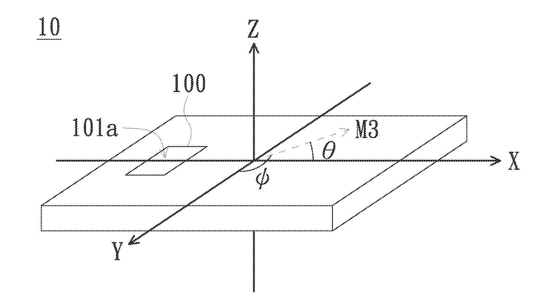
[0015]The present invention provides a magnetic-field sensing method using a planar magnetoresistive sensor to sense two-dimensional magnetic-field components in parallel with the substrate plane to further estimate the three-dimensional magnetic field above the substrate plane.

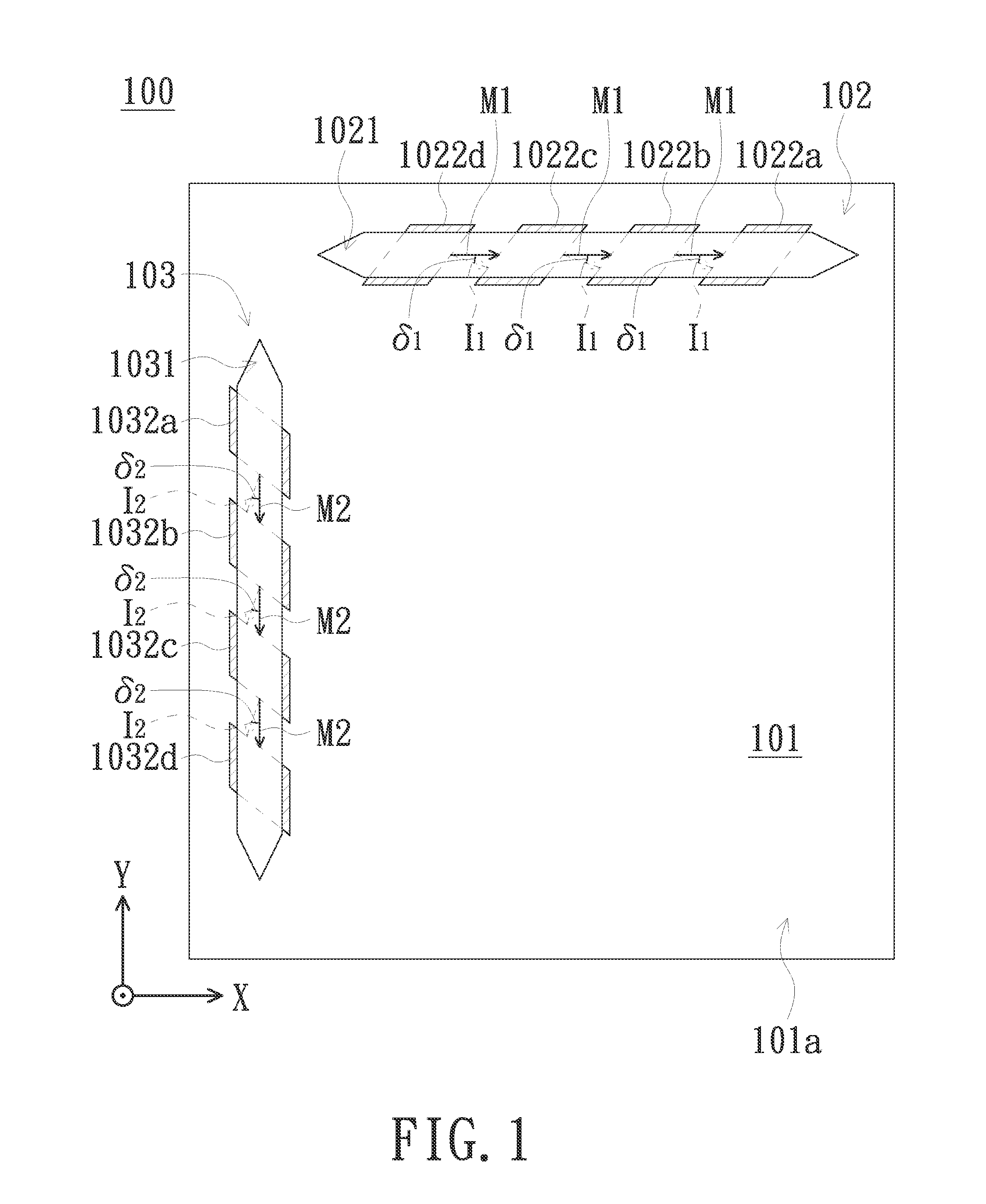
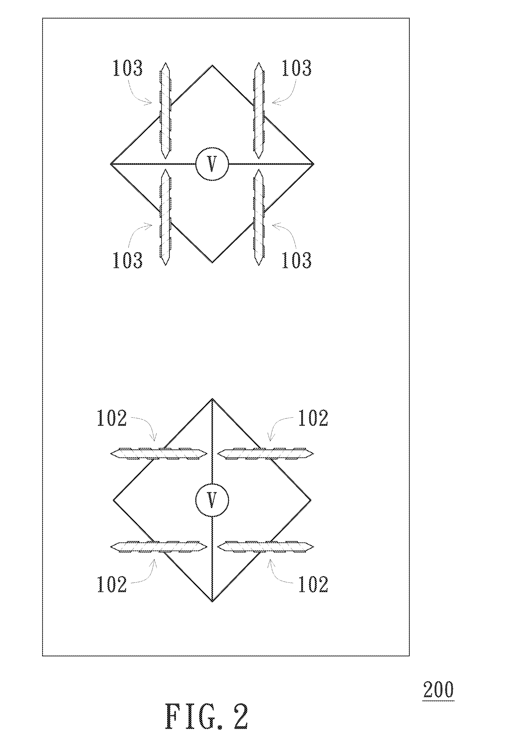
[0016]The magnetic-field sensing method comprises the following steps. First, a magnetoresistive sensing device is provided. Please refer to FIG. 1, which is a top view of a magnetoresistive sensing device 100 according to one embodiment of the present invention. The magnetoresistive sensing device 100 comprises at least a first magnetoresistive sensing un...


PUM


Abstract

A magnetoresistive sensing device is provided. A first sensed magnetic-field component in parallel with the x-axis and a second sensed magnetic-field component in parallel with the y-axis of an external magnetic field forming a first inclination angle with the x-axis and a second inclination angle with the y-axis are determined. A virtual plane is defined so as to render a magnetic-field component perpendicular to the virtual plane of the external magnetic field is essentially zero. The first inclination angle and the second inclination angle are adjusted with reference to the virtual plane. An x-axis magnetic-field component in parallel with the x-axis, a y-axis magnetic-field component in parallel with the y-axis and a z-axis magnetic-field component in parallel with the z-axis of the external magnetic field are estimated according to the adjusted first inclination angle, the adjusted second inclination angle, the first sensed magnetic-field component and the second sensed magnetic-field component.

Description

FIELD OF THE INVENTION[0001]The present invention relates to a magnetic-field sensing method, and more particularly to a method for sensing a three-dimensional magnetic field by using a two-dimensional magnetoresistive sensing device.BACKGROUND OF THE INVENTION[0002]With the development of consumer electronic products such as mobile phones and electronic compasses and the use of conventional products such as motors and actuators, the need of magnetoresistive sensors has grown. More particularly, three-dimensional magnetoresistive sensors are capable of sensing the variations of the magnetic field components along the x-axis, the y-axis and the z-axis that are perpendicular to one another. An electronic compass uses a three-dimensional magnetoresistive sensor to precisely sense the terrestrial magnetic field.[0003]Current three-dimensional magnetoresistive sensing devices have been well-developed. However, most of the conventional arts use multi-chip or three-dimensional structured m...

Claims


Application Information

Patent Timeline
Patent Type & Authority Applications(United States)
IPC IPC(8): G01R33/02G01R33/09G01C17/02
CPCG01R33/0206G01R33/09G01C17/02G01C17/28G01R33/093
Inventor KUO, MING-YU
Owner VOLTAFIELD TECH
Why Eureka
Try Eureka