Fuel injection system for a turbine engine

a technology for turbine engines and fuel injection systems, which is applied in the direction of hot gas positive displacement engine plants, combustion processes, lighting and heating apparatus, etc. it can solve the problems of excessive leaning of nozzles designed to run at full load, high co production of lean flames, and limited air flow by igvs, etc., to achieve constant fuel ratio, improve efficiency, and reduce nox emissions

Inactive Publication Date: 2015-05-14
SIEMENS AG
View PDF5 Cites 2 Cited by
  • Summary
  • Abstract
  • Description
  • Claims
  • Application Information

AI Technical Summary

Benefits of technology

[0006]A fuel system for a turbine engine for improving the efficiency in a fuel system where a major stage and secondary stage can be combined and held to a relatively constant fuel ratio while maintaining acceptable engine dynamics and NOx emissions is disclosed. The fuel system may be formed from a first premix injector assembly stage positioned upstream from a combustor basket, whereby the first premix injector assembly stage is a secondary injector system. The fuel system may be formed from a first primary injector assembly stage, which is a main injector system, positioned downstream from the first premix injector assembly. The first premix injector assembly stage and the first primary injector assembly stage may be coupled together such that the fuel system is capable of emitting fuel into a combustor of the turbine engine via the first premix injector assembly stage and the primary injector assembly stage simultaneously.

Problems solved by technology

However, because lean flames have a low flame temperature, lean flames are prone to high CO production.
And because excess CO production is harmful, a need exists to limit CO emissions.
Thus, nozzles designed to run at full load run excessively lean at partial loads.
However, IGVs may only be used to restrict air flow a limited amount.

Method used


Image

  • Fuel injection system for a turbine engine
  • Fuel injection system for a turbine engine
  • Fuel injection system for a turbine engine

Examples


Embodiment Construction

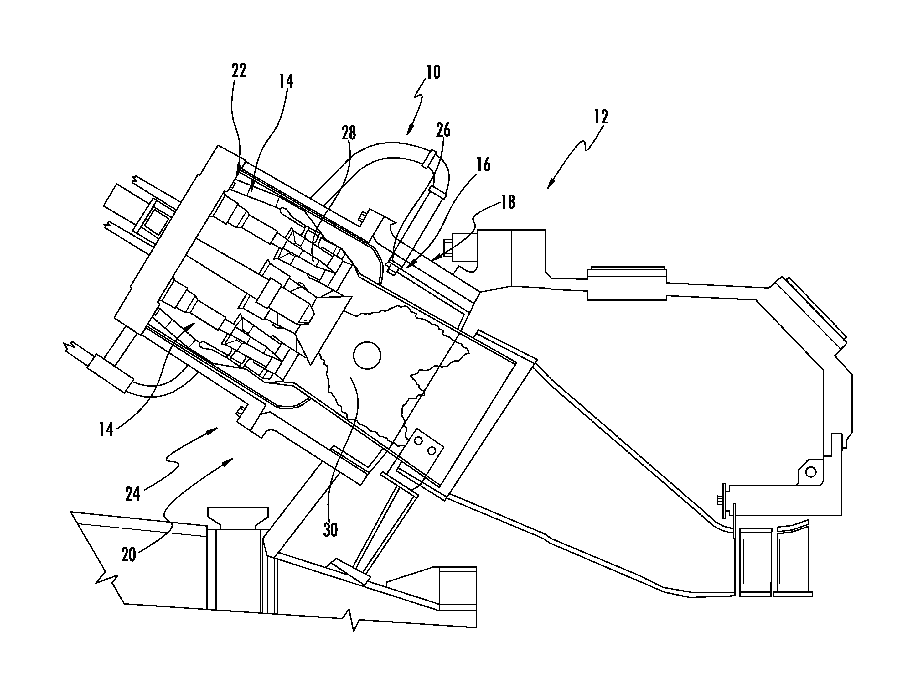
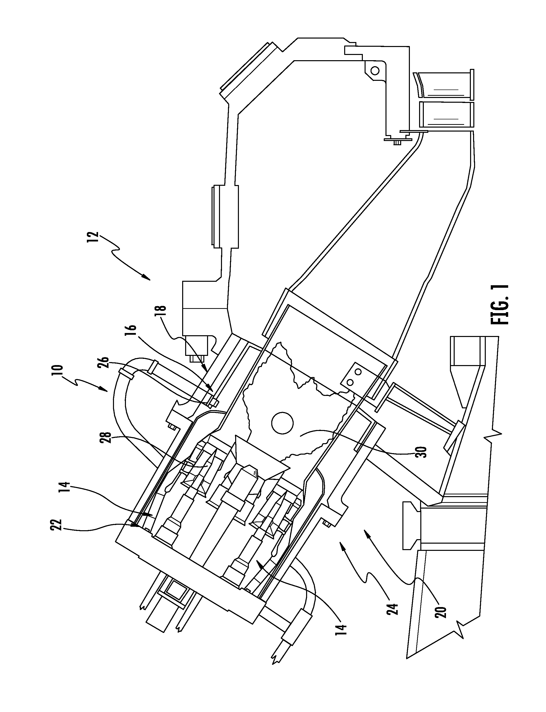
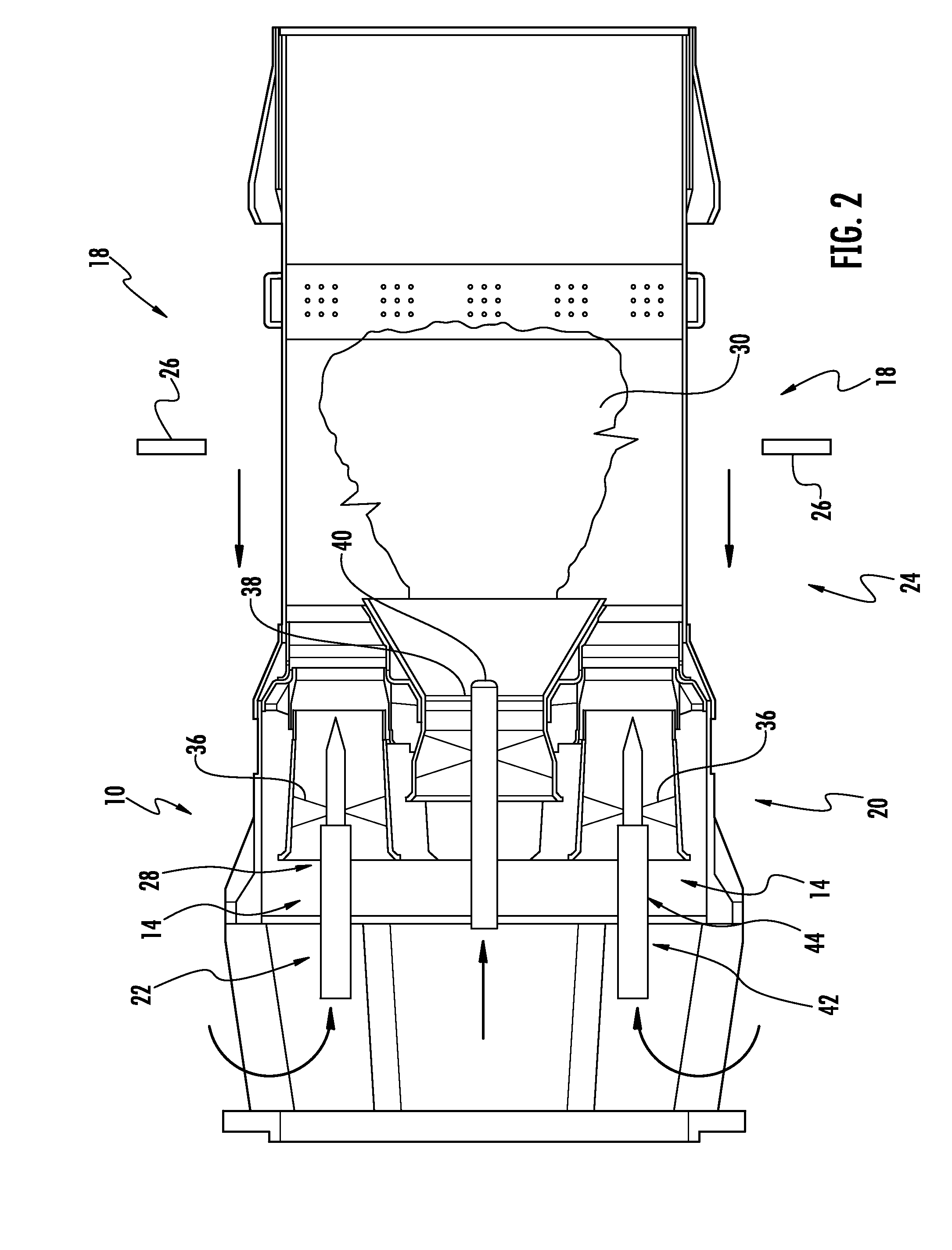
[0020]As shown in FIGS. 1-6, a fuel system 10 for a turbine engine 12 for improving the efficiency in the fuel system 10 where a major stage 14 and secondary stage 16 can be combined and held to a relatively constant fuel ratio while maintaining acceptable engine dynamics and NOx emissions is disclosed. The fuel system 10 may be formed from a first premix injector assembly stage 18 positioned upstream from a combustor basket 20, whereby the first premix injector assembly stage 18 is a secondary injector system. The fuel system 10 may be formed from a first primary injector assembly stage 22, which is a primary injector system, positioned downstream from the first premix injector assembly stage 18. The first premix injector assembly stage 18 and the first primary injector assembly stage 22 may be coupled together such that the fuel system 10 is capable of emitting fuel into a combustor 24 of the turbine engine 12 via the first premix injector assembly stage 18 and the primary injecto...


PUM


Abstract

A fuel system for a turbine engine for improving efficiency in a fuel system where a major stage and secondary stage can be combined and held to a relatively constant fuel ratio while maintaining acceptable engine dynamics and NOx emissions is disclosed. The fuel system may be formed from a first premix injector assembly stage positioned upstream from a combustor basket, whereby the first premix injector assembly stage is a secondary injector system. The fuel system may be formed from a first primary injector assembly stage, which is a main injector system, positioned downstream from the first premix injector assembly stage. The first premix injector assembly stage and the first primary injector assembly stage may be coupled together such that the fuel system is capable of emitting fuel into a combustor of the turbine engine via the first premix injector assembly stage and the first primary injector assembly stage simultaneously.

Description

FIELD OF THE INVENTION[0001]This invention is directed generally to turbine engines, and more particularly to fuel system for turbine engines.BACKGROUND[0002]Typically, gas turbine engines include a plurality of injectors for injecting fuel into a combustor to mix with air upstream of a flame zone. The fuel injectors of conventional turbine engines may be arranged in one of at least three different schemes. Fuel injectors may be positioned in a lean premix flame system in which fuel is injected in the air stream far enough upstream of the location at which the fuel / air mixture is ignited that the air and fuel are completely mixed upon burning in the flame zone. Fuel injectors may also be configured in a diffusion flame system such that fuel and air are mixed and burned simultaneously. In yet another configuration, often referred to as a partially premixed system, fuel injectors may inject fuel upstream of the flame zone a sufficient distance that some of the air is mixed with the fu...

Claims


Application Information

Patent Timeline
Patent Type & Authority Applications(United States)
IPC IPC(8): F23R3/28
CPCF23R3/286F23R3/346
Inventor MIDUTURI, KRISHNA C.WASIF, SAMER P.
Owner SIEMENS AG
Why Eureka
Try Eureka