Brake

a technology of control mechanism and brake, which is applied in the direction of brake system, braking system, electrical apparatus, etc., to achieve the effects of preventing noise, safe and reliable operation, and preventing noise produced by the brak

Active Publication Date: 2015-05-14
KONE CORP
View PDF21 Cites 17 Cited by
  • Summary
  • Abstract
  • Description
  • Claims
  • Application Information

AI Technical Summary

Benefits of technology

[0012]According to the invention the braking function can be soundlessly activated by displacing the initial position of the drop-out movement / the braking piece in the initial position of the drop-out movement from the releasing position into the braking position in a controlled manner with a predetermined movement profile implemented by the actuator, with which profile the striking of the surfaces of the brake against each other, and the disturbing noise produced by this, is prevented. Likewise, the brake can be soundlessly released by displacing the initial position of the drop-out movement / the braking piece in the initial position of the drop-out movement from the braking position into the releasing position in a controlled manner with a predetermined movement profile implemented by the actuator.
[0013]At the same time safe operation of the brake is ensured with the drop-out apparatus, which drops the braking piece to displace from the initial position of the drop-out movement into the braking position when a triggering means is controlled immediately an operational anomaly / possible dangerous situation is detected. Consequently, the brake of an elevator according to the invention can, during normal operation of the elevator, be controlled soundlessly with the actuator and when an operational anomaly of the elevator is detected the brake can be dropped, in which case the braking piece displaces into the braking position and braking starts as quickly as possible when the braking piece strikes the braking surface from the effect of spring force. The disturbing noise produced by release of the braking piece can be accepted in an operational anomaly of the elevator, because it is more important than the noise nuisance in this case to provide for the safety of the elevator and for the braking to start as quickly and reliably as possible. Owing to the safe and reliable operation described above, the brake according to the invention is also suited for use as a mechanical safety device of an elevator.

Problems solved by technology

Owing to the imbalance of forces the brake pad strikes against the braking surface of the rotating part of the machine.

Method used


Image

  • Brake
  • Brake
  • Brake

Examples


Embodiment Construction

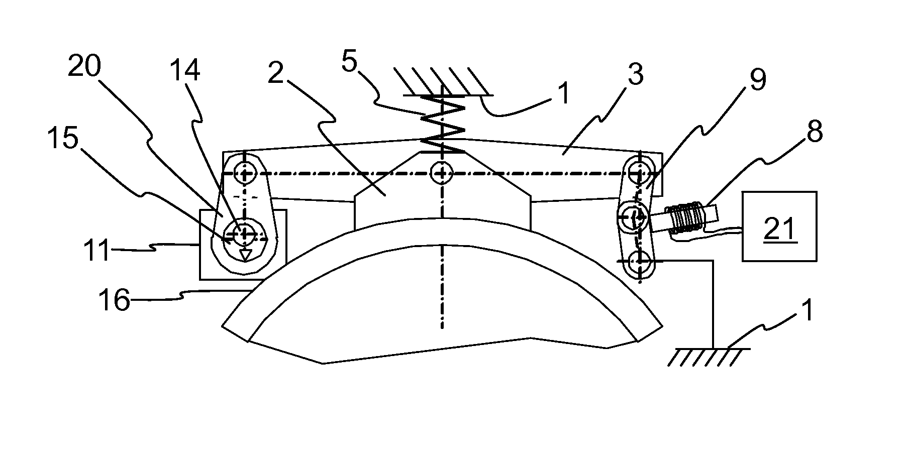
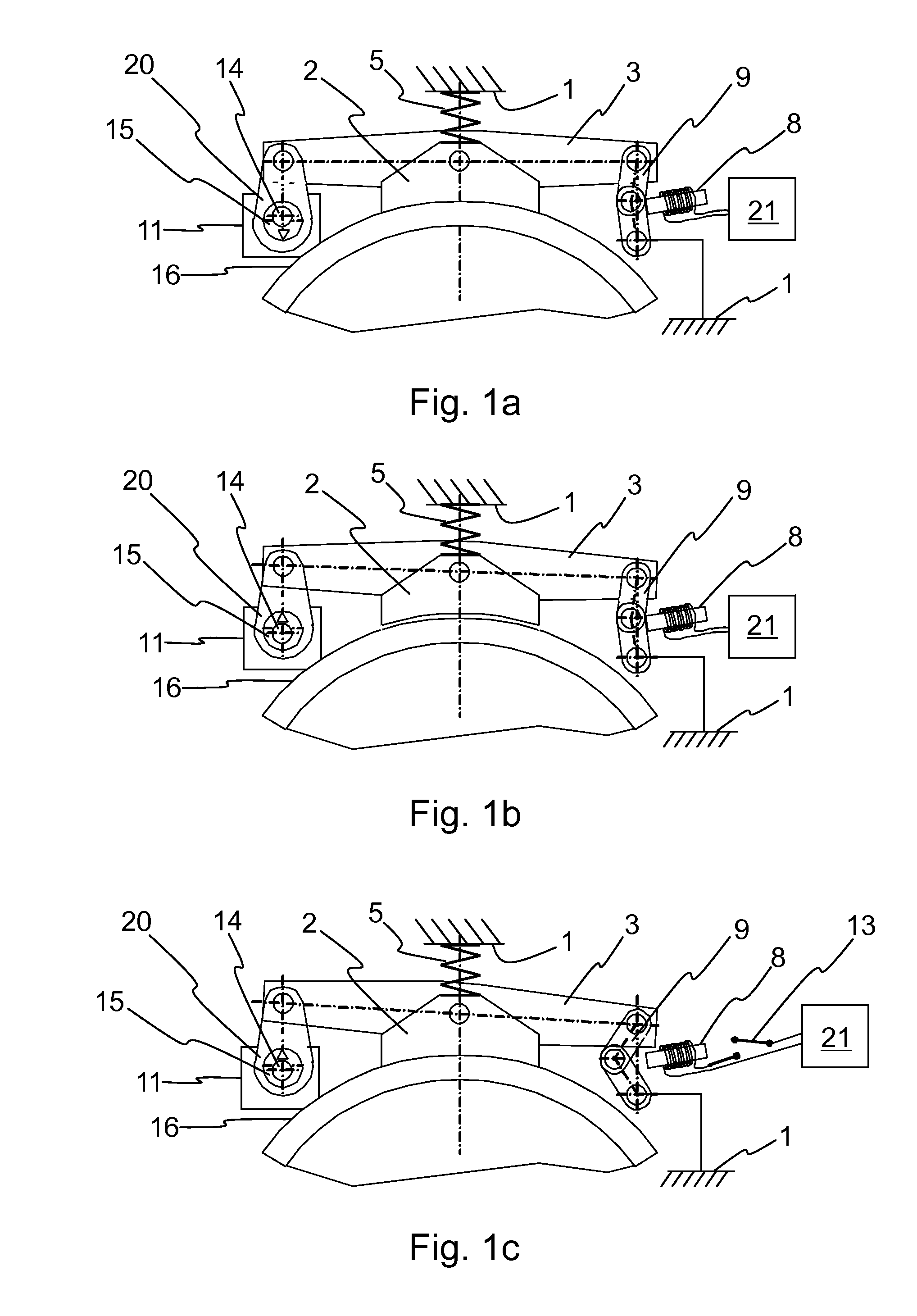
[0023]FIGS. 1a-1c present a shoe brake of a hoisting machine of an elevator in different operating situations such that

[0024]FIG. 1a presents a situation in which the brake is activated to brake the hoisting machine of the elevator in connection with normal operation of the elevator,

[0025]FIG. 1b presents a situation in which the brake is released in connection with normal operation of the elevator, and

[0026]FIG. 1c presents a situation in which the brake is dropped and the drop-out movement of the brake has occurred as a consequence of a operational anomaly of the elevator.

[0027]The brake control mechanism according to FIGS. 1a-1c can also be fitted to a disc brake, instead of a shoe brake, e.g. such that one of the braking pieces on opposite sides of the brake disc is configured to be controlled with a control mechanism according to FIGS. 1a-1c.

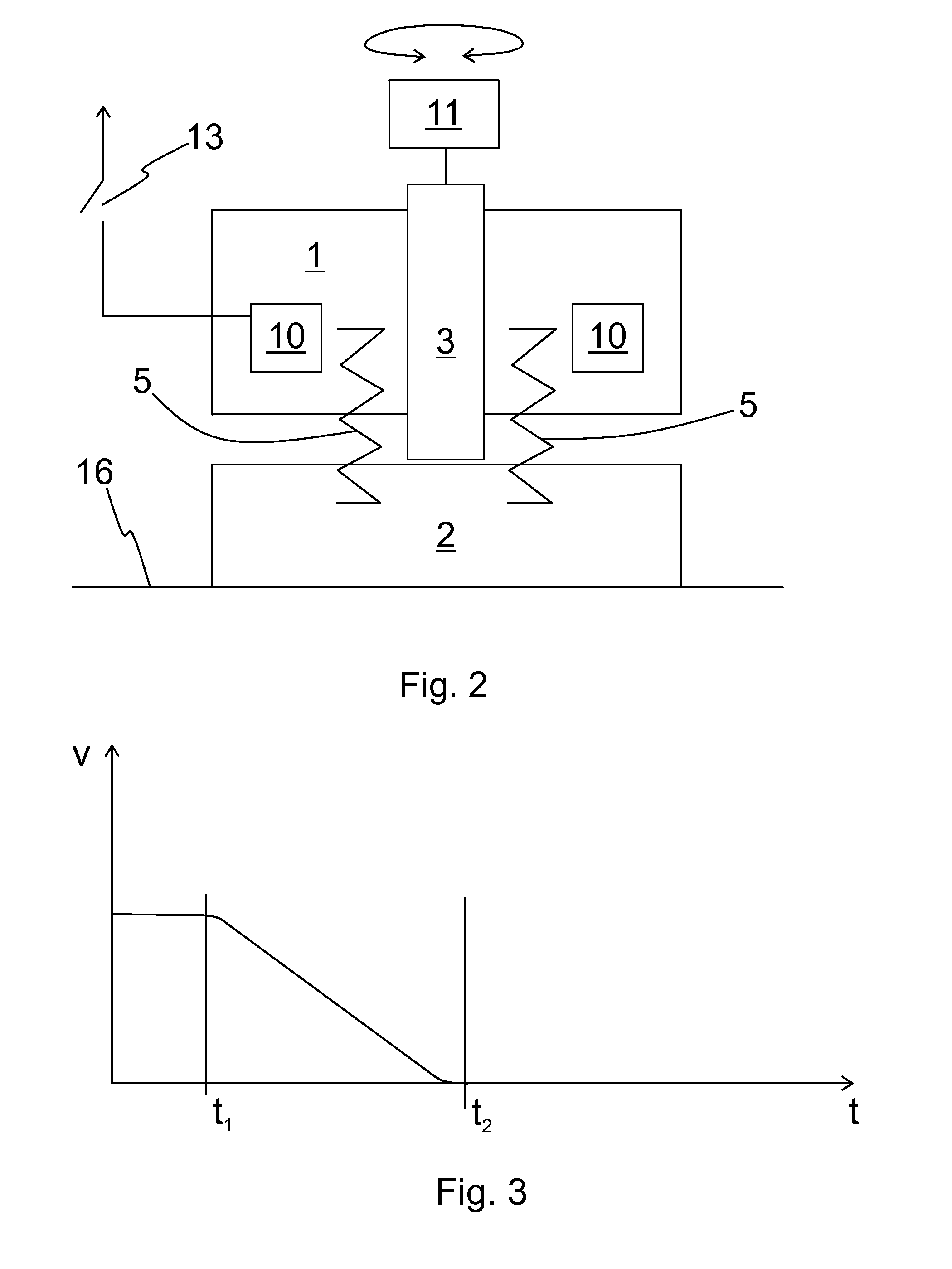
[0028]The hoisting machine of an elevator means a drive device with which an elevator car is driven in a vertical direction in an elevato...


PUM


Abstract

The invention relates to a brake and to a method for controlling the brake. The brake comprises a base part, a braking piece movably supported on the base part, which braking piece is configured to be moved between a braking position and a releasing position, a spring, with the spring force of which the braking piece can be dropped into a braking position, a support member for limiting the initial position of the drop-out movement of the braking piece and also a controllable actuator, which is mechanically connected to the aforementioned support member and configured to displace the initial position of the drop-out movement of the braking piece with respect to the braking position.

Description

FIELD OF THE INVENTION[0001]The invention relates to brakes and more particularly to the control mechanisms of brakes to be used as safety devices.BACKGROUND OF THE INVENTION[0002]In an elevator hoisting machine, for example, a machinery brake that mechanically engages with a rotating part of the hoisting machine is normally used as a brake device. Structurally, the machinery brake can be e.g. a shoe brake, a drum brake or a disc brake.[0003]The machinery brake generally comprises springs, which push a braking piece provided with a brake pad against the braking surface of a rotating part to brake the movement of the rotating part of the hoisting machine. A machinery brake generally also comprises an electromagnet, with which a braking piece provided with a magnetic core is pulled against the thrusting force of the springs into a releasing position of the brake away from the braking surface. The machinery brake is dropped by disconnecting the current supply of the electromagnet of th...

Claims


Application Information

Patent Timeline
Patent Type & Authority Applications(United States)
IPC IPC(8): B66B5/02
CPCB66B5/02B60T1/04B61H1/00B66B1/32B66D5/08B66D5/30F16D59/02F16D65/0006F16D65/06F16D2121/26F16D2125/26F16D2125/645F16D2127/008H02P15/00F16D65/22B66B5/18F16D65/00
Inventor OLKKONEN, MIKAALKULA, PETRIPELTO-HUIKKO, RAIMO
Owner KONE CORP
Why Eureka
Try Eureka