Screen printing machine, electronic component mounting system, and screen printing method

Active Publication Date: 2015-05-14
PANASONIC INTELLECTUAL PROPERTY MANAGEMENT CO LTD
View PDF69 Cites 14 Cited by
  • Summary
  • Abstract
  • Description
  • Claims
  • Application Information

AI Technical Summary

Benefits of technology

[0012]According to aspects of the present invention, it is possible to prevent unevenne

Problems solved by technology

In recent years, with the demand of productivity increase and increased difficulty of printing due to reduction of the pitches of printing portions on boards, it has become an important issue to supply sufficient amounts of paste to printing portions even in the case of a high-speed squeegeeing operation.
However, in the above-described technique, the angle formed by the top surface of the mask plate and the filling surface of the fil

Method used


Image

  • Screen printing machine, electronic component mounting system, and screen printing method
  • Screen printing machine, electronic component mounting system, and screen printing method
  • Screen printing machine, electronic component mounting system, and screen printing method

Examples


Example

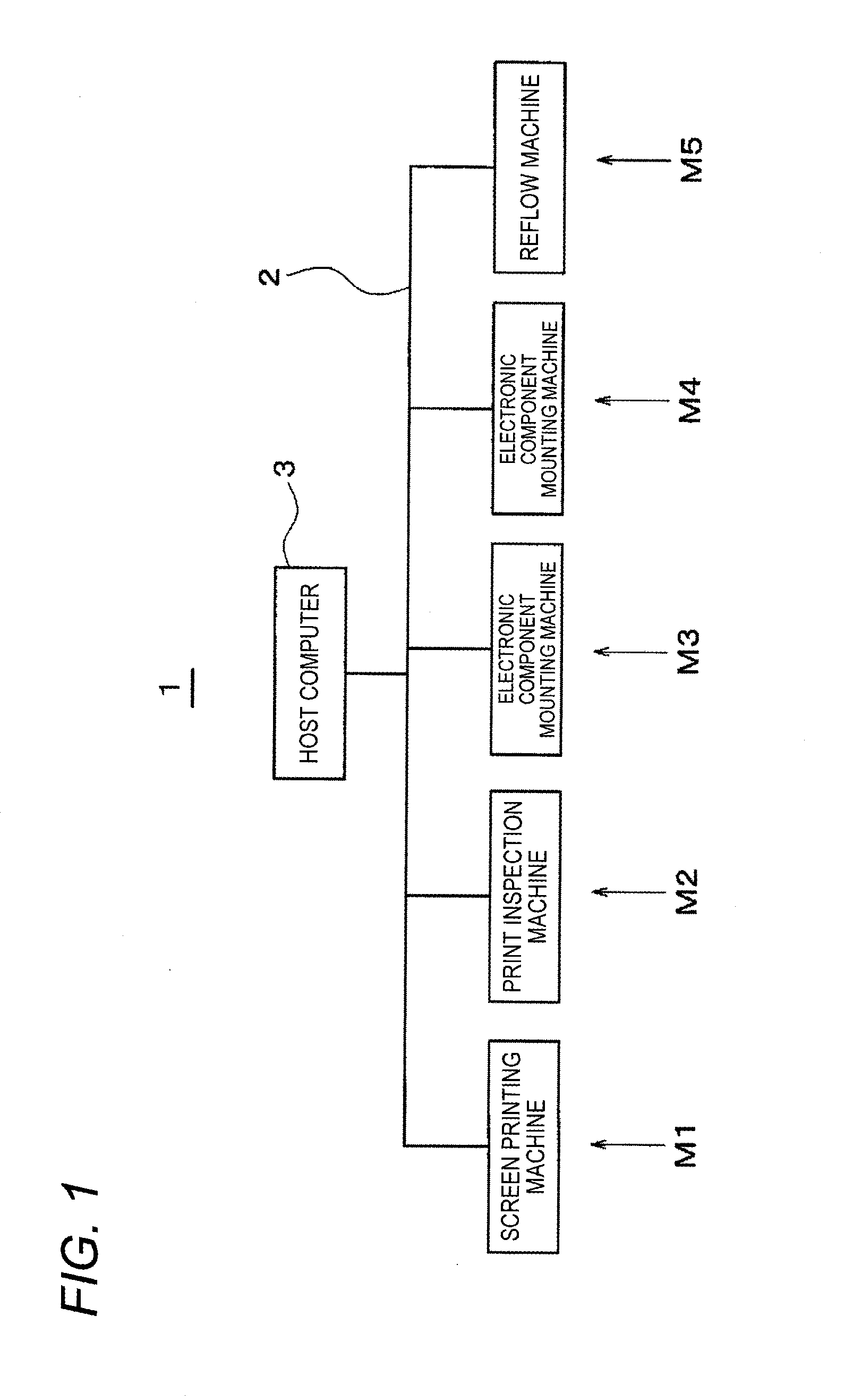
[0024]First, the overall configuration of an electronic component mounting system will be described with reference to FIG. 1. The electronic component mounting system 1 has a function of mounting an electronic component on a board via paste such as cream solder. Plural component mounting machines including a screen printing machine M1, a print inspection machine M2, electronic component mounting machines M3 and M4, and a reflow machine M5 are connected together in cascade and connected to each other by a communication network 2 so as to be controlled as a whole by a host computer 3.

[0025]The screen printing machine M1 screen-prints paste layers on electronic component joining electrodes formed on a board. The print inspection machine M2 performs print inspection including judgment as to whether or not the paste layers formed on the board are in good print states and detection of deviations of printed paste layers from electrodes. The electronic component mounting machines M3 and M4 ...


PUM

PropertyMeasurementUnit
Pressureaaaaaaaaaa
Flexibilityaaaaaaaaaa

Abstract

A screen printing machine for forming a print of paste supplied to a mask plate having pattern holes, includes: a flexible filling squeegee which performs a squeegeeing operation in which the filling squeegee is moved relative to the mask plate in a printing direction; and a scraping squeegee which is held to maintain a given interval from the filling squeegee in the printing direction and to be movable together with the filling squeegee in the printing direction, and which scraps off the paste remaining on the mask plate after passage of the filling squeegee. In the squeegeeing operation, the filling squeegee is pushed up and bent by the paste to provide a clearance between a bottom end of the filling squeegee and the mask plate with the paste interposed therebetween so that the pattern holes are filled with paste with a prescribed filling pressure.

Description

BACKGROUND[0001]1. Technical Field[0002]An aspect of the present invention relates to a screen printing machine for forming a print of paste such as cream solder on a board. Another aspect of the present invention relates to an electronic component mounting system including the screen printing machine. Yet another aspect of the invention relates to a screen printing method.[0003]2. Description of Related Art[0004]Screen printing is known as a method for forming a print of paste such as cream solder or conductive paste on a board in an electronic component mounting process. In this method, a paste print is formed on a board through pattern holes that are formed so as to conform to print subject portions. A paste print is formed on a board that is set on the bottom surface of a mask plate by filling the pattern holes with paste by a squeegeeing operation of moving a spatula-shaped squeegee member in a horizontal direction with its bottom end pressed against the mask plate.[0005]In rec...

Claims


Application Information

Patent Timeline
IPC IPC(8): B23K3/06H05K3/34H05K13/04B41F15/44
CPCB23K3/0638H05K13/0465H05K3/34B41F15/44B23K1/0016H05K3/1233H05K3/3485H05K2203/0139
Inventor KURODA, SEIYATANAKA, TETSUYATOMOMATSU, MICHINORI
Owner PANASONIC INTELLECTUAL PROPERTY MANAGEMENT CO LTD
Why Eureka
Try Eureka