Automatic shock absorber system for bicycle

a bicycle and automatic control technology, applied in the field of bicycle suspension systems, can solve the problems of inability to make timely adjustment of front shock absorber, inability to coordinate front and rear shock absorber, and inability to ride a bicycle in the mountain as stable as driving a four-wheel drive vehicle, so as to improve pedaling efficiency and improve riding safety

Active Publication Date: 2015-05-14
GIANT MFG
View PDF13 Cites 18 Cited by
  • Summary
  • Abstract
  • Description
  • Claims
  • Application Information

AI Technical Summary

Benefits of technology

[0032]Based on the above, automatically adjusting the level of the damping force according to the sensed information described above allows the user not to pay attention to controlling switching of the level of the damping force. Therefore, the pedaling efficiency is improved, and riding becomes safer as well.

Problems solved by technology

However, an issue set forth in the following may arise in the conventional technology of shock absorber adjustment.
Accordingly, the front shock absorber is not able to make a timely adjustment, making the front and rear shock absorber not coordinated properly.
Moreover, the front wheel of a bicycle has a turning function, and riding a bicycle in the mountain is not as stable as driving a four-wheel vehicle.
Besides, there is no consistent pattern for judgments in the signals received and in actual bicycle-riding in the wild, and the signals received need some time to be analyzed.
Thus, in a complicated pavement condition, it is almost impossible for a control mechanism to correspond to the condition simultaneously.
Accordingly, the method using the acceleration of the front wheel to detect the bumpiness of the pavement does not yield a preferable result.

Method used


Image

  • Automatic shock absorber system for bicycle
  • Automatic shock absorber system for bicycle
  • Automatic shock absorber system for bicycle

Examples


first embodiment

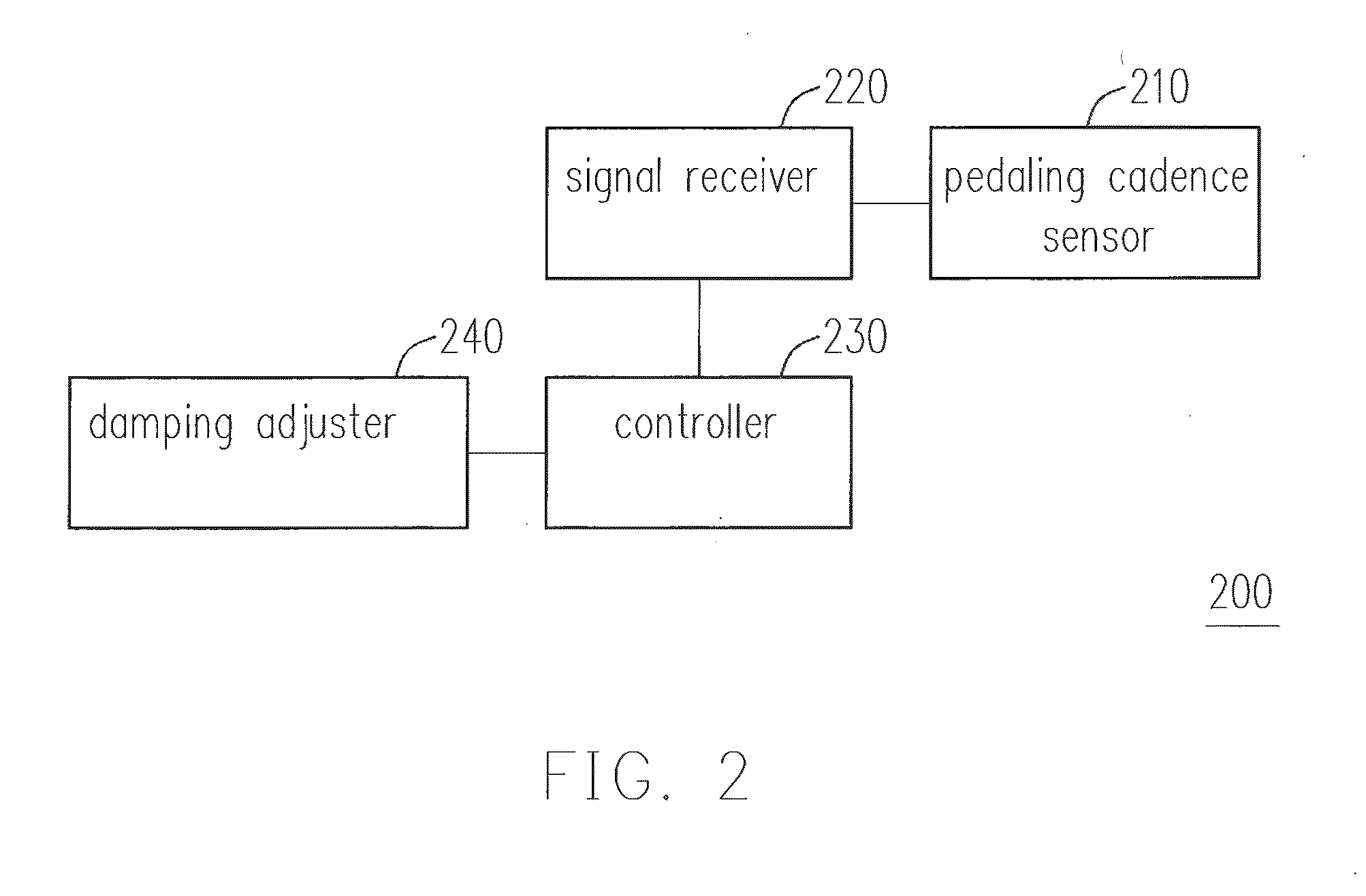
[0067]FIG. 2 is a block diagram illustrating an automatic control shock absorber system for a bicycle according to the first embodiment. In this embodiment, an automatic control shock absorber system 200 for a bicycle includes a pedaling cadence sensor 210, a signal receiver 220, a controller 230, and a damping adjuster 240.

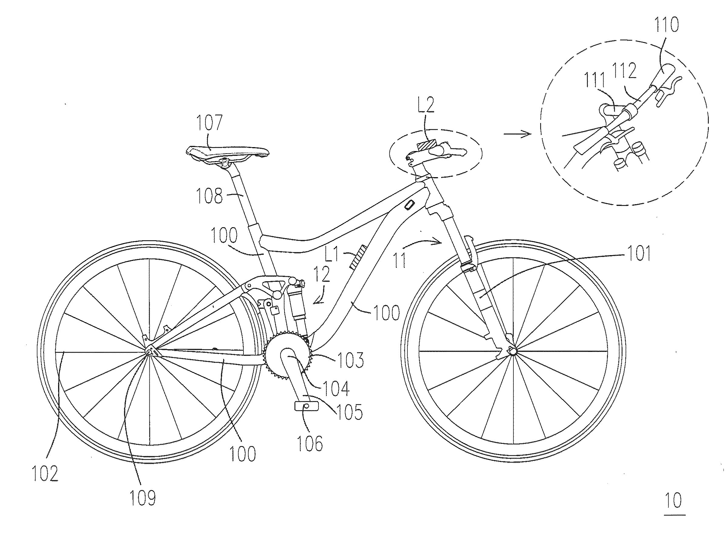
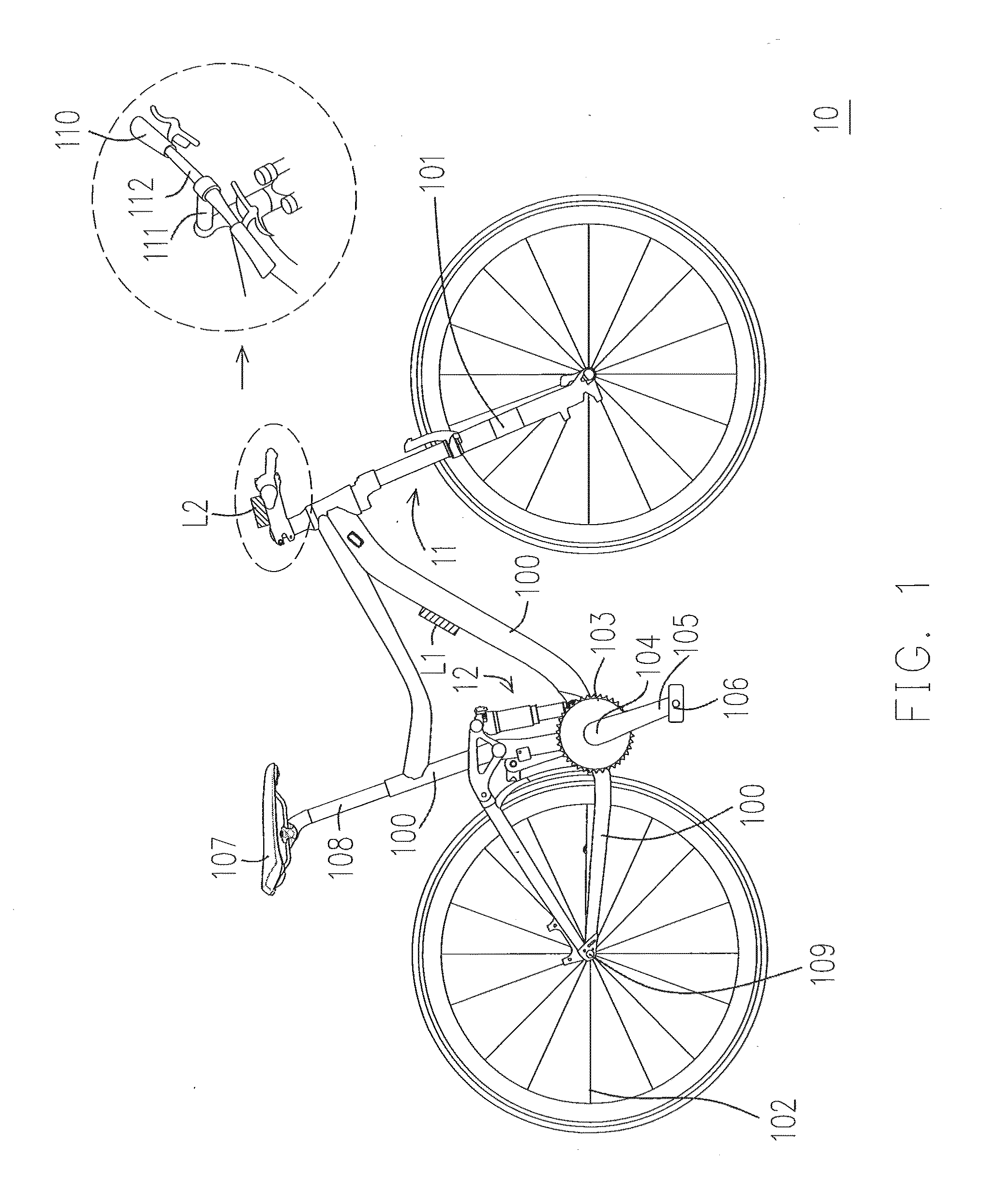
[0068]The pedaling cadence sensor 210 is configured to detect a pedaling cadence of the bicycle 10 and output a pedaling signal. The pedaling cadence sensor 210 may be disposed at one of the chain ring 103, the crank spindle 104, the crank arm 105, the pedal 106, and the frame 100, etc., of the bicycle 10. In addition, the pedaling cadence sensor 210 may also be disposed at a leg, such as both legs (e.g. inner sides of thighs) of the rider, or on a shoe of the rider.

[0069]The signal receiver 220 is coupled to the pedaling cadence sensor 210 and the controller 230 to receive and transmit the pedaling signal to the controller 230. Here, the signal receiver 220 may ...

second embodiment

[0079]FIGS. 4A and 4B are block diagrams illustrating an automatic control shock absorber system for a bicycle according to the second embodiment. In FIG. 4A, an automatic control shock absorber system 400 for a bicycle includes a posture sensor 410, the signal receiver 220, the controller 230, and the damping adjuster 240. Here, components having the same functions as those described in the first embodiment are referred to with the same reference symbols, and description relevant to the components is omitted.

[0080]The posture sensor 410 is configured to detect whether the rider adopts a standing posture or a sitting posture when riding the bicycle 10, and output a posture signal. The signal receiver 220 is coupled to the posture sensor 410 to receive the posture signal. The controller 230 is coupled to the signal receiver 220 and output the level control signal to the damping adjuster 240, such that the damping adjuster 240 adjusts the level of the damping force according to the le...

third embodiment

[0091]FIG. 6 is a block diagram illustrating an automatic control shock absorber system for a bicycle according to the third embodiment. An automatic control shock absorber system for a bicycle of the embodiment includes the pedaling cadence sensor and a slope sensor. Referring to FIG. 6, an automatic control shock absorber system 600 for a bicycle includes the pedaling cadence sensor 210, a slope sensor 610, the signal receiver 220, the controller 230, and the damping adjuster 240. Here, components having the same functions as those described in the first embodiment are referred to with the same reference symbols, and description relevant to the components is omitted.

[0092]The slope sensor 610 is configured to detect a slope of a location of the bicycle 10 and output a slope signal, such that the slope signal is transmitted to the controller 230 through the signal receiver 220. Here, the controller 230 determines a relational curve of damping according to the slope signal, and outp...


PUM


Abstract

An automatic control shock absorber system for a bicycle is provided. The system includes one or more sensors. A controller outputs a control signal to a damping adjuster according to the one or more sensors, such that the damping adjuster controls level of damping force based on the sensors.

Description

CROSS REFERENCE TO RELATED APPLICATIONS[0001]This application claims the priority benefit of Taiwan Application Serial No. 102141089, filed on Nov. 12, 2013 and Taiwan Application Serial No. 103126190, filed on Jul. 31, 2014. The entirety of the two above-mentioned patent application is hereby incorporated by reference herein in their entirety.BACKGROUND[0002]1. Field[0003]The technology described herein relates to a vehicle suspension system, and particularly relates to an automatic control shock absorber system for a bicycle.[0004]2. Description of the Related Art[0005]The conventional suspension control method for a bicycle makes use of a shock signal of a front wheel to open or switch a valve of a shock absorber, or uses shock acceleration of the front wheel to determine bumpiness of pavements, thereby controlling the valve of the shock absorber and thus adjusting the shock absorbing ability and reacting speed of the shock absorber.[0006]However, an issue set forth in the follow...

Claims


Application Information

Patent Timeline
Patent Type & Authority Applications(United States)
IPC IPC(8): B62K25/04
CPCB62K2025/044B62K25/04B60G17/016B60G17/0165B60G17/06B60G2300/12
Inventor CHEN, CHIEN-HUNGCHEN, MIN-CHANGLIN, CHUNG-WEI
Owner GIANT MFG
Why Eureka
Try Eureka