Method and apparatus for producing diffusion aluminide coatings

Active Publication Date: 2015-05-14
PRAXAIR ST TECH INC
View PDF1 Cites 6 Cited by
  • Summary
  • Abstract
  • Description
  • Claims
  • Application Information

AI Technical Summary

Benefits of technology

[0014]In a first aspect, a method for applying an aluminide coating is provided. The coating process comprises providing a component having an external section and an internal section. The internal section is characterized by one or more internal surfaces defining an internal cavity. An elongated member defined at least in part by a size and shape corresponding to the internal section of the component is also provided. The elongated member is applied with an aluminum-based slurry onto the elongated member. The elongated member is introduced through an opening of said component and then positioned into said cavity at a location that is spaced apart from each of the one or more internal surfaces. Heat is applied to the component and the member. Vaporized aluminum is generated within said internal section and directed towards the one or more internal surfaces. The vaporized aluminum is diffused into the one or more surfaces. The aluminum reacts with the one or more surfaces to form the aluminide coating.
[0015]In a second aspect, a method for applying an aluminide coating is provided. The coating process comprises providing a component having an external section and an internal section, in which the internal section is characterized by one or more internal surfaces defining a first internal cavity and a second internal cavity. A first elongated member is provided. The first elongated member is defined at least in part by a size and shape corresponding to the first internal cavity. A first aluminum-based slurry is applied onto said first elongated member. A second elongated member is defined at least in part by the size and shape corresponding to the second internal cavity. A second aluminum-based slurry is applied onto said second elongated member. The first elongated member is introduced into the first internal cavity. The first elongated member is positioned within said first cavity at a first location that is spaced apart from each of the one or more internal surfaces defining the first internal cavity. The second elongated member is introduced into the second internal cavity

Problems solved by technology

In particular, oxidation and corrosion reactions at the surface of the component parts can cause metal wastage and loss of wall thickness.
The loss of metal rapidly increases the stresses on the respective component part and can result in part failure.
Furthermore, excessively thick aluminide coatings, especially at leading and trailing edges of turbine blades where high stresses mostly occur, can result in fatigue cracking.
As a result, the internal surfaces of the hollow components must be coated in a way that not only produces uniform thickness coatings, but leaves unobstructed the cooling air passages along the internal surfaces.
Advancements in the aerospace industry have led to gas turbine components which are designed with increasingly complicated geometries along surfaces of the internal cavities, thereby making the ability to uniformly coat such surfaces more challenging than previously encountered.
However, an undesirable residual coating, some of which may be referred to as “bisque” in the industry, can be difficult to remove from the cooling air holes and internal passages.
Bisque can cause restriction of air flow.
As a result, the part must be scrapped, thereby causing material an

Method used


Image

  • Method and apparatus for producing diffusion aluminide coatings
  • Method and apparatus for producing diffusion aluminide coatings
  • Method and apparatus for producing diffusion aluminide coatings

Examples


example 1

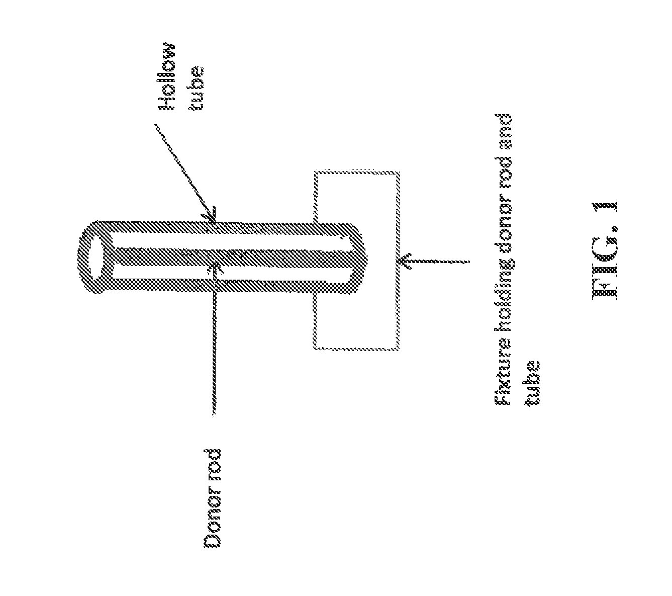
Indirect Slurry Rod Method for Coating Hollow Tubes

[0048]Tests were performed to apply an aluminide coating onto the internal surfaces of a hollow cylindrical tube. The tube was identical to the one coated in Comparative Example 1. A representative schematic of the tube is shown in FIG. 1. The tube was formed from grade 304 stainless steel. The tube was 48 inches in length and had a diameter of 2 inches.

[0049]A cylindrical shaped elongated member of grade 304 stainless steel was coated with SermAlcote™ 2525 slurry aluminide. The member was dipped into the slurry to produce a film thickness of approximately 0.01 inches. The member was cured at 250° F. for 1 hour. The coated member was placed inside the hollow tube and positioned so as to not contact the walls of the tube. A heat-resistant metal fixture was configured at each end of the tube to maintain the tube in a fixed position during the coating cycle.

[0050]The coating assembly was then introduced into a bell retort furnace. The ...

example 2

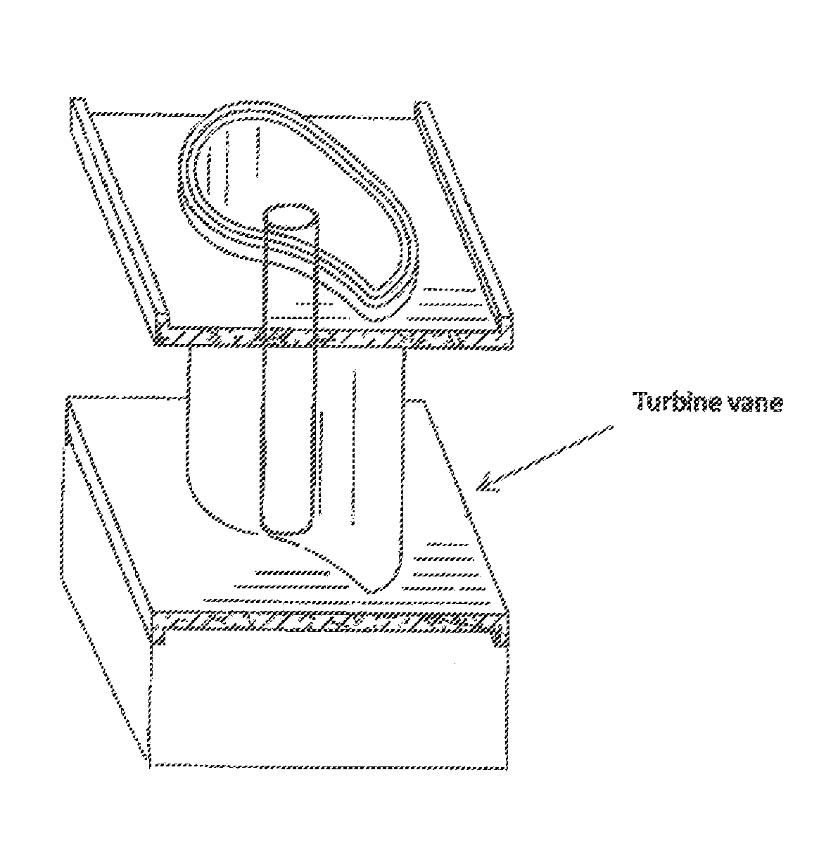
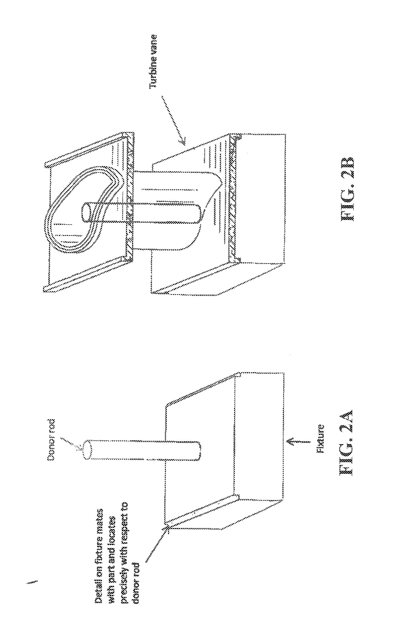
Indirect Slurry Rod Method for Coating Turbine Vane

[0053]Two trials were performed to apply an aluminide coating onto the internal surfaces of a gas turbine vane having a geometry identical to that of Comparative Example 2. The coating material was SermAlcote™ 2525 aluminide.

[0054]A stainless steel wire was coated with SermAlcote™ 2525 slurry aluminide. The wire had a diameter of 0.125 inches. The wire was dipped into the slurry to produce a film thickness of approximately 0.01 inches. The wire was cured at 250° F. for 1 hour. Next, the turbine vane was placed over the rod. A heat-resistant graphite fixture was configured to maintain the tube in a fixed position during the coating cycle. The coated wire was positioned so as to not contact the walls of the vane.

[0055]The coating assembly was then introduced into a bell retort furnace. The coating and hollow tube were heat treated in the bell retort furnace for 1975° F. for 6 hours in an argon atmosphere. Aluminum vaporized from the s...


PUM

PropertyMeasurementUnit
Thicknessaaaaaaaaaa
Sizeaaaaaaaaaa
Heataaaaaaaaaa

Abstract

Unique and improved methods and coating apparatuses for applying diffusion aluminide materials onto internal sections of various parts are disclosed. The source material is coated onto an elongated member, such as a wire or rod, which is subsequently inserted at a specific location into a hollow cavity of the component to be coated. Improvements in the coating process and resultant coating include the ability to coat complex geometries and coat components with uniform thicknesses that do not require post-coating steps for removal of oxides and/or residual bisque.

Description

[0001]The present application claims priority from U.S. Provisional Application Ser. No. 61 / 901,573, filed Nov. 8, 2013, which is incorporated by reference herein in its entirety.FIELD OF THE INVENTION[0002]The present invention relates to novel and improved methods and coating apparatuses for applying a controlled amount of diffusion coating material onto surfaces of an internal cavity, such as the internal sections of gas turbine components.BACKGROUND OF THE INVENTION[0003]Aluminide coatings are diffused coatings widely used to protect metallic substrate surfaces, such as nickel, cobalt, iron and copper alloys. Aluminide coatings are based on intermetallic compounds formed when nickel and cobalt react with aluminum at the substrate's surface. An intermetallic compound is an intermediate phase in a binary metallic system, having a characteristic crystal structure enabled by a specific elemental (atomic) ratio between the binary constituents.[0004]Aluminum-based intermetallic compou...

Claims


Application Information

Patent Timeline
IPC IPC(8): C23C14/04C23C14/14C23C14/24
CPCC23C14/046C23C14/14C23C14/243C23C10/28C23C10/30C23C10/48
Inventor GARING, KEVIN E.MCCONNELL, JEFFREY J.HUTZLER, III, CARL HUGO
Owner PRAXAIR ST TECH INC
Why Eureka
Try Eureka