Apparatus and method for ultrasonic diagnosis

a technology of ultrasonic diagnosis and apparatus, applied in the field of apparatus and method for ultrasonic diagnosis, can solve the problems of difficult pressure application to cause a sufficient displacement, limited imaging subject, and increased local temperature in the interior of a living body, and achieve the effect of high-precision evaluation of a viscosity parameter

Inactive Publication Date: 2015-05-14
HITACHI LTD
View PDF15 Cites 11 Cited by
  • Summary
  • Abstract
  • Description
  • Claims
  • Application Information

AI Technical Summary

Benefits of technology

[0013]According to the present disclosure, it is possible to highly accurately evaluate a v

Problems solved by technology

This method has a problem in that a subject for imaging is limited to organs in the areas to which pressure is easily applied from the body surface.
For example, since a slip surface exists as an intermediate layer between a body surface and a liver, it is difficult to apply pressure to cause a sufficient displacement.
As described above, since the total application time period of the pushing b

Method used


Image

  • Apparatus and method for ultrasonic diagnosis
  • Apparatus and method for ultrasonic diagnosis
  • Apparatus and method for ultrasonic diagnosis

Examples


first embodiment

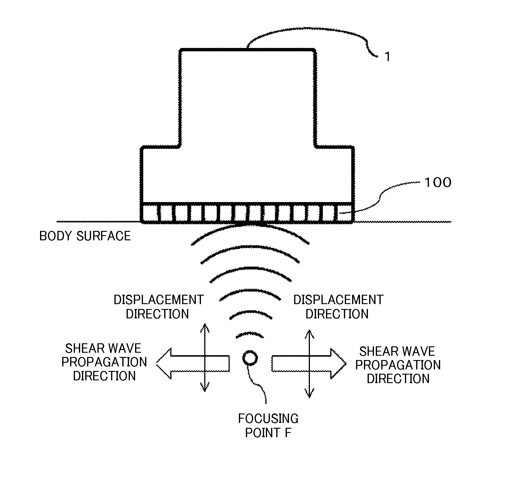
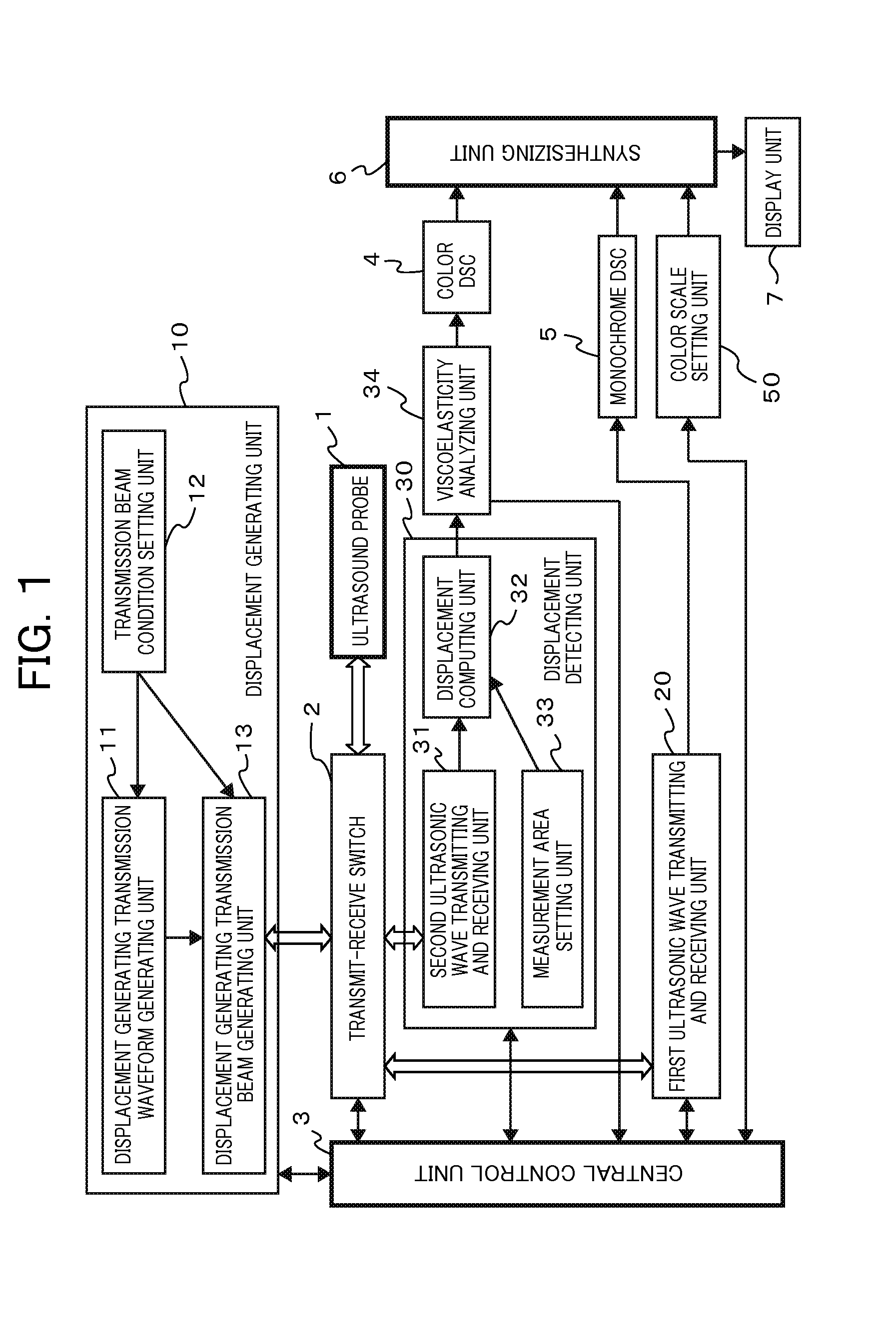
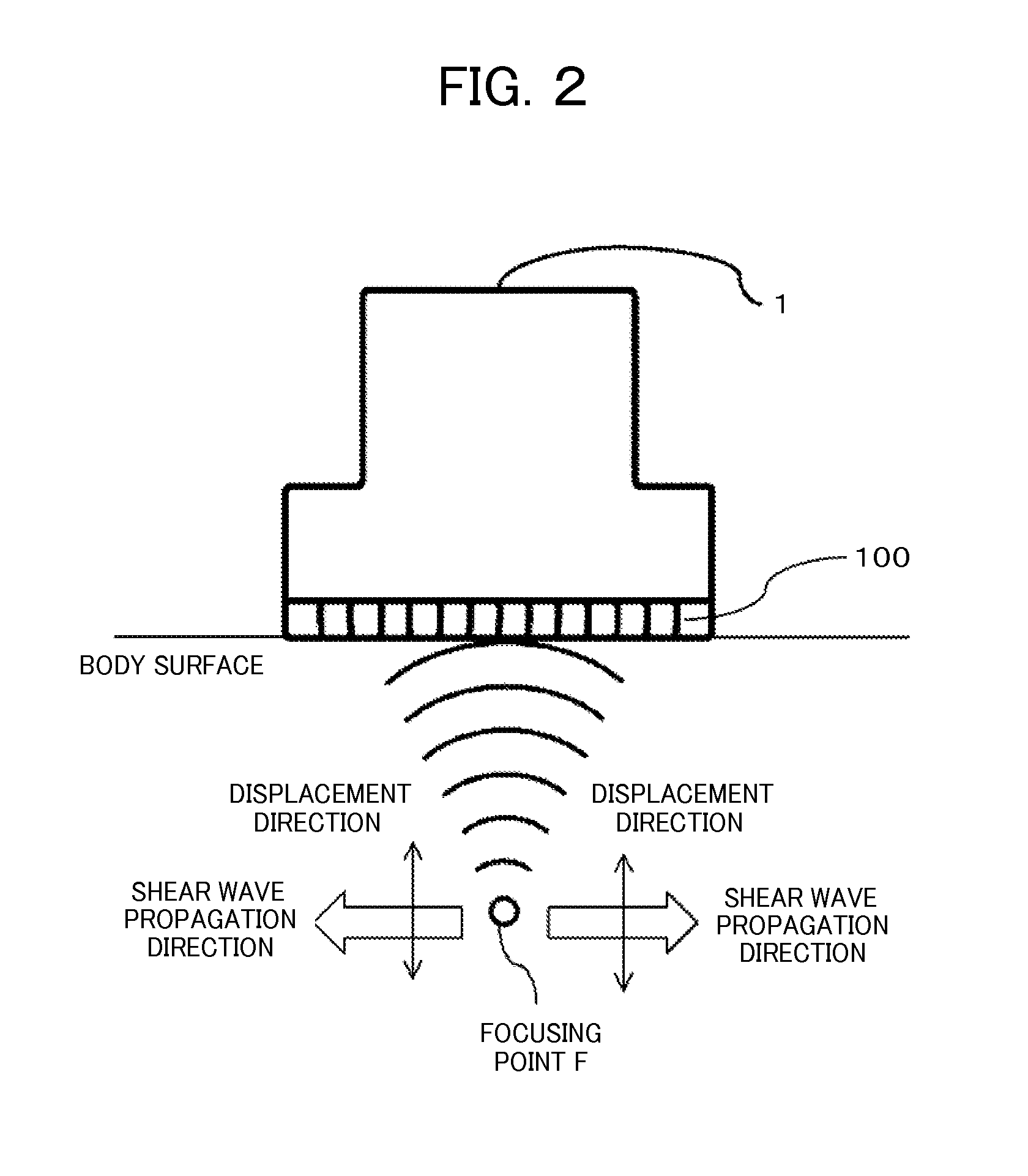
[0043]A first embodiment is an embodiment of an ultrasonic diagnostic apparatus and a method for estimating a viscosity parameter. The ultrasonic diagnostic apparatus includes a displacement generating unit 10 that applies an acoustic radiation pressure to the interior of an examinee to cause displacement, a displacement detecting unit 30 that transmits and receives an ultrasonic wave at a plurality of positions, at least two or more of positions, on the examinee and detects the particle velocity of a shear wave generated in the interior of the examinee, and a viscoelasticity analyzing unit 34 that estimates a viscosity parameter from the particle velocity, in which the viscoelasticity analyzing unit 34 estimates a viscosity parameter from a temporal extent of a waveform of the particle velocity.

[0044]FIG. 1 is an exemplary overall structure of the apparatus according to the first embodiment. An ultrasound probe 1 is used in contact with the skin of an examinee, not illustrated, and...

second embodiment

[0075]A second embodiment is an embodiment of an apparatus and a method for ultrasonic diagnosis. The apparatus includes a displacement generating unit 10 that applies an acoustic radiation pressure to the interior of an examinee to cause displacement, a displacement detecting unit 30 that transmits and receives an ultrasonic wave at a plurality of positions, at least two or more of positions, on the examinee and detects the particle velocity of a shear wave generated in the interior of the examinee, a viscoelasticity analyzing unit 34 that estimates a viscosity parameter from the particle velocity, and a feedback parameter determining unit 38, in which the viscoelasticity analyzing unit 34 estimates a viscosity parameter from the temporal extents of waveforms of the particle velocity, and the feedback parameter determining unit 38 adjusts at least one of a transmission condition and a region of interest in a second measurement, which is the subsequent measurement, based on the visc...


PUM


Abstract

When subject tissue such as a living body is a viscoelastic body, a shear wave propagation velocity is changed according to the frequency of a shear wave. An ultrasonic diagnostic apparatus applies a displacement generating transmission beam from an ultrasound probe based on a signal from a displacement generating unit to generate a shear wave, applies a pulse wave to the biological tissue by a displacement detecting unit, detects the particle velocity of the shear wave, estimates a viscosity parameter from a temporal extent of a waveform of the particle velocity of the shear wave detected at a viscoelasticity analyzing unit, and displays the estimated viscoelasticity on a display unit.

Description

CLAIM OF PRIORITY[0001]The present application claims priority from Japanese Patent Application JP 2013-232539 filed on Nov. 8, 2013, the content of which is hereby incorporated by reference into this application.BACKGROUND OF THE INVENTION[0002]The present disclosure relates to a technique that measures the viscoelasticity of an examinee by transmitting and receiving ultrasonic waves.[0003]There is a method (an elastography technique) for diagnosing the stiffness of the interior of an examinee from ultrasonic echo signals instead of palpation by a doctor as a diagnostic method for breast cancer, hepatic cirrhosis, angiopathy, and so on. In the diagnosis of stiffness according to the elastography technique, a medical practitioner holds an ultrasound probe against the body surface of a living body, which is an examinee, and applies pressure to cause displacement to tissue in the interior of the examinee. A displacement in the compression direction is estimated from echo signals befor...

Claims


Application Information

Patent Timeline
IPC IPC(8): A61B8/08A61B8/00
CPCA61B8/485A61B8/54A61B8/469A61B8/5223A61B8/5207G01S7/52022G01S7/52042G01S7/52071G01S15/8915G16H50/30
Inventor TABARU, MARIEYOSHIKAWA, HIDEKITANAKA, HIROKI
Owner HITACHI LTD
Why Eureka
Try Eureka