Machine-to-machine plant automation using 3D printed fiber splicing

a technology of 3d printing and plant automation, applied in the direction of manufacturing tools, instruments, other domestic articles, etc., can solve the problems of expensive cleaning materials and receptacles, difficult patching of optical fibers, and large manual labor and training

Active Publication Date: 2015-05-21
VERIZON PATENT & LICENSING INC
View PDF6 Cites 10 Cited by
  • Summary
  • Abstract
  • Description
  • Claims
  • Application Information

AI Technical Summary

Problems solved by technology

While electronic cross-overs may be used to handle metal patch automation in electrical communication networks, patching of optical fibers has been problematic.
Patching of optical fibers may require a large amount of manual labor and training, as well as costly cleaning materials and receptacles.
Other problems associa

Method used


Image

  • Machine-to-machine plant automation using 3D printed fiber splicing
  • Machine-to-machine plant automation using 3D printed fiber splicing
  • Machine-to-machine plant automation using 3D printed fiber splicing

Examples


Embodiment Construction

[0017]The following detailed description refers to the accompanying drawings. The same reference numbers in different drawings identify the same or similar elements.

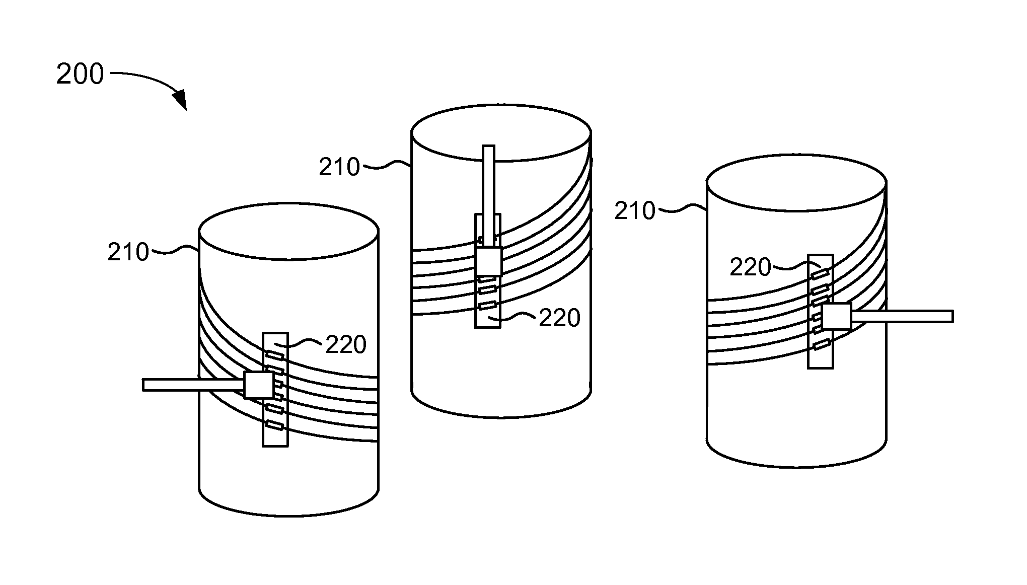
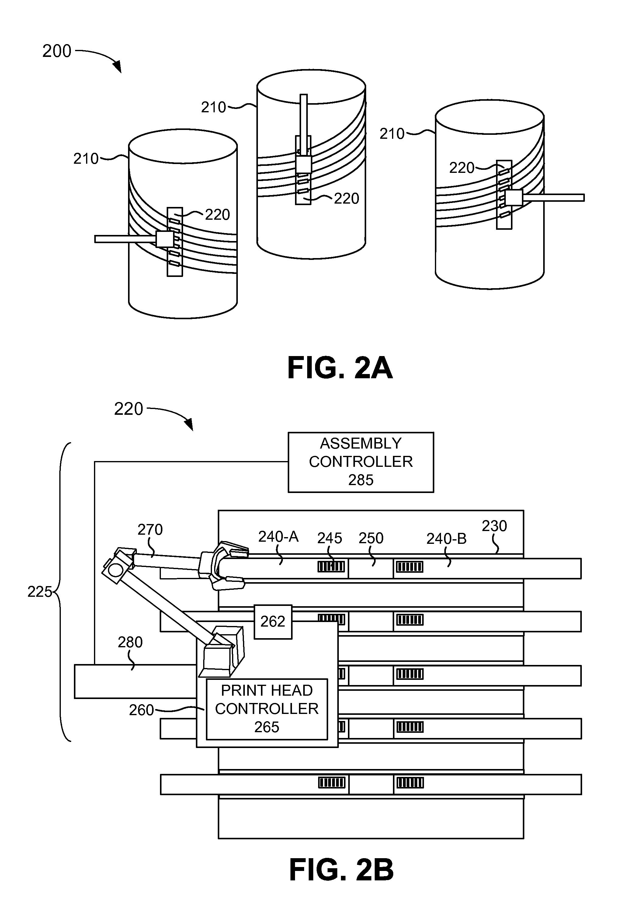
[0018]Implementations described herein relate to three dimensional (3D) printed splicing of optical fibers and to machine-to-machine plant automation using 3D printed optical fiber splicing. A fiber splicing machine may be used to align optical fibers for splicing and to clean the ends of the fibers in preparation for splicing. In some implementations, a pre-mold may be added to the junction site in order to speed up the splicing process. The fiber splicing machine may then use a print head with a silane material, such as a chlorinated polysilane material, to 3D print a silica junction between optical fibers to splice the optical fibers together. After the print head ejects beads or droplets of the silane material, the silane material may cure to a silica glass material. After the silica junction is printed, the print he...


PUM

PropertyMeasurementUnit
Refractionaaaaaaaaaa

Abstract

A system may include a fiber distribution hub including a plurality of fiber-optic cables, wherein a particular one of the plurality of fiber-optic cables includes a machine-readable identifier; and a robotic device configured to access particular ones of the plurality of fiber-optic cables. The robotic device may include a print head configured to splice together the particular ones of the plurality of fiber-optic cables by three-dimensional printing of a silane material. A hand-held unit may also include a print head configured to splice together fiber-optic cables by three-dimensional printing of a silane material.

Description

BACKGROUND INFORMATION[0001]Optical fiber networks are used by providers of telecommunication services for transmission across the core and to the edge of telecommunication networks. While electronic cross-overs may be used to handle metal patch automation in electrical communication networks, patching of optical fibers has been problematic. Patching of optical fibers may require a large amount of manual labor and training, as well as costly cleaning materials and receptacles. Other problems associated with patching of optical fibers include loss of signal at fiber junctions, human errors during fiber splicing, and the high cost of fiber splicing equipment. The high cost and time requirements to patch optical fibers have impacted the installation, maintenance, repair, and reconfiguration of optical fiber networks.BRIEF DESCRIPTION OF THE DRAWINGS[0002]FIG. 1 is a diagram illustrating an environment according to an implementation described herein;[0003]FIGS. 2A and 2B are diagrams il...

Claims


Application Information

Patent Timeline
IPC IPC(8): G02B6/255B29D11/00
CPCG02B6/2553G02B6/2555B29D11/00961B29D11/00865B29D11/00663B33Y30/00B29D11/0075B29K2075/00B29K2083/00B29K2101/00B29K2105/0058B29K2995/0018B33Y10/00B33Y50/02B33Y80/00
Inventor PEREZ, JOHN SCOTT
Owner VERIZON PATENT & LICENSING INC
Why Eureka
Try Eureka