
System and method for power conversion

a power conversion and system technology, applied in the field of power conversion systems, can solve the problems of increasing the footprint of the inverter, increasing the cost, and reducing the power conversion efficiency of the inverter, and achieve the effect of reducing the common mode signal

Inactive Publication Date: 2015-05-21
GENERAL ELECTRIC CO
View PDF7 Cites 8 Cited by
  • Summary
  • Abstract
  • Description
  • Claims
  • Application Information

AI Technical Summary

Benefits of technology

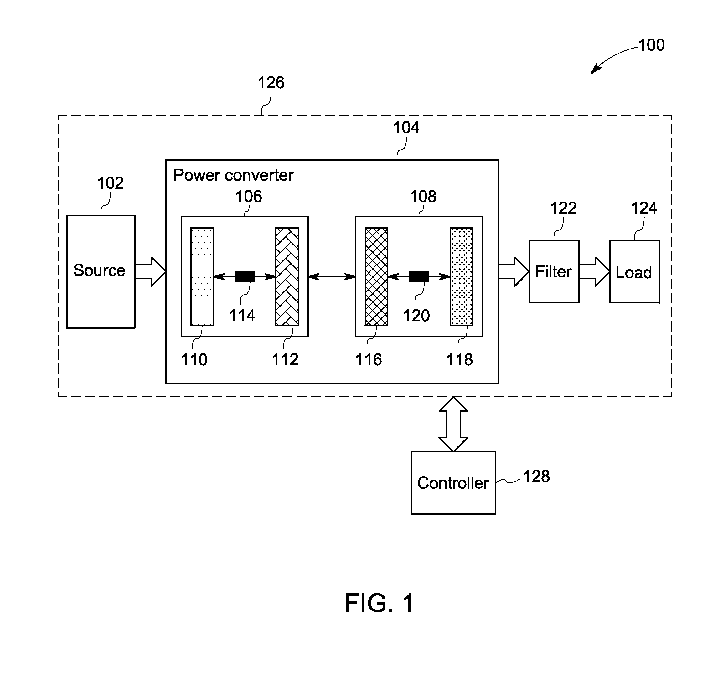
The patent describes a method for improving the efficiency of power conversion by reducing common mode signals. It involves coupling multiple circuits together, each containing at least two semiconductor switches. The method includes using a controller to create a switching pattern for each semiconductor switch in each circuit, and then selectively switching each switch based on the pattern to reduce the common mode signal. This results in a more efficient power conversion system.

Problems solved by technology

The use of transformers in the inverters not only results in an increased footprint of the inverters, but also increases cost and lowers power conversion efficiency of the inverters.
The high frequency common mode voltage signal disadvantageously results in a high leakage current.
Also, the high frequency common mode voltage signals result in complications due to electromagnetic interference (EMI).
Unfortunately, the high leakage currents in the inverters using unipolar PWM render these inverters less suitable for transformer-less inverter applications.
Furthermore, use of bipolar PWM in the inverters results in a reduction of the common mode signal.
Accordingly, the efficiency of these inverters is diminished.
Also, the size and the cost of the inverter increases.

Method used


Image

  • System and method for power conversion
  • System and method for power conversion
  • System and method for power conversion

Examples


Embodiment Construction

[0016]Unless defined otherwise, technical and scientific terms used herein have the same meaning as is commonly understood by one of ordinary skill in the art to which this disclosure belongs. The terms “first”, “second”, and the like, as used herein do not denote any order, quantity, or importance, but rather are used to distinguish one element from another. Also, the terms “a” and “an” do not denote a limitation of quantity, but rather denote the presence of at least one of the referenced items. The term “or” is meant to be inclusive and mean one, some, or all of the listed items. The use of “including,”“comprising” or “having” and variations thereof herein are meant to encompass the items listed thereafter and equivalents thereof as well as additional items. The terms “connected” and “coupled” are not restricted to physical or mechanical connections or couplings, and can include electrical connections or couplings, whether direct or indirect. Furthermore, the terms “circuit” and ...


PUM


Abstract

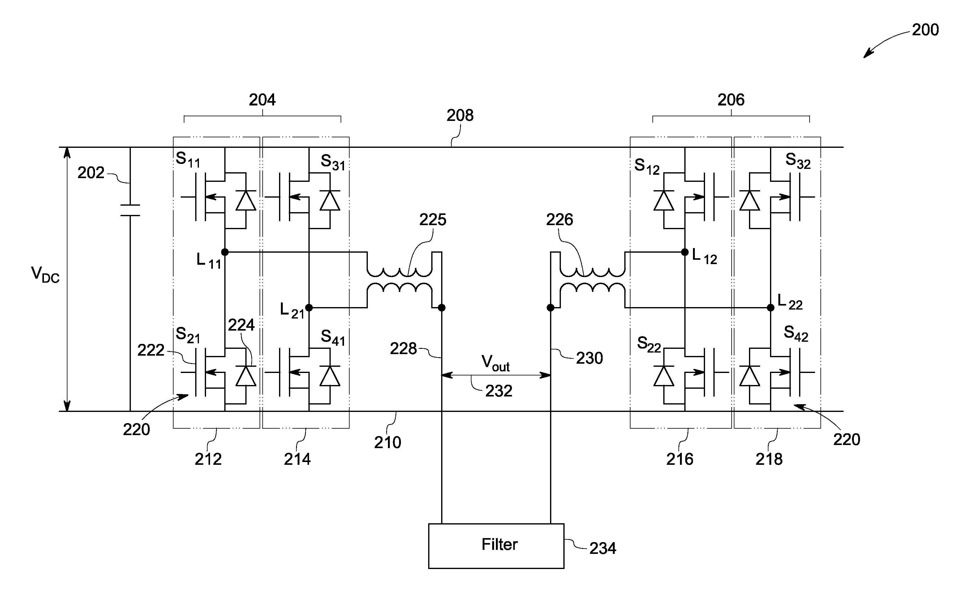
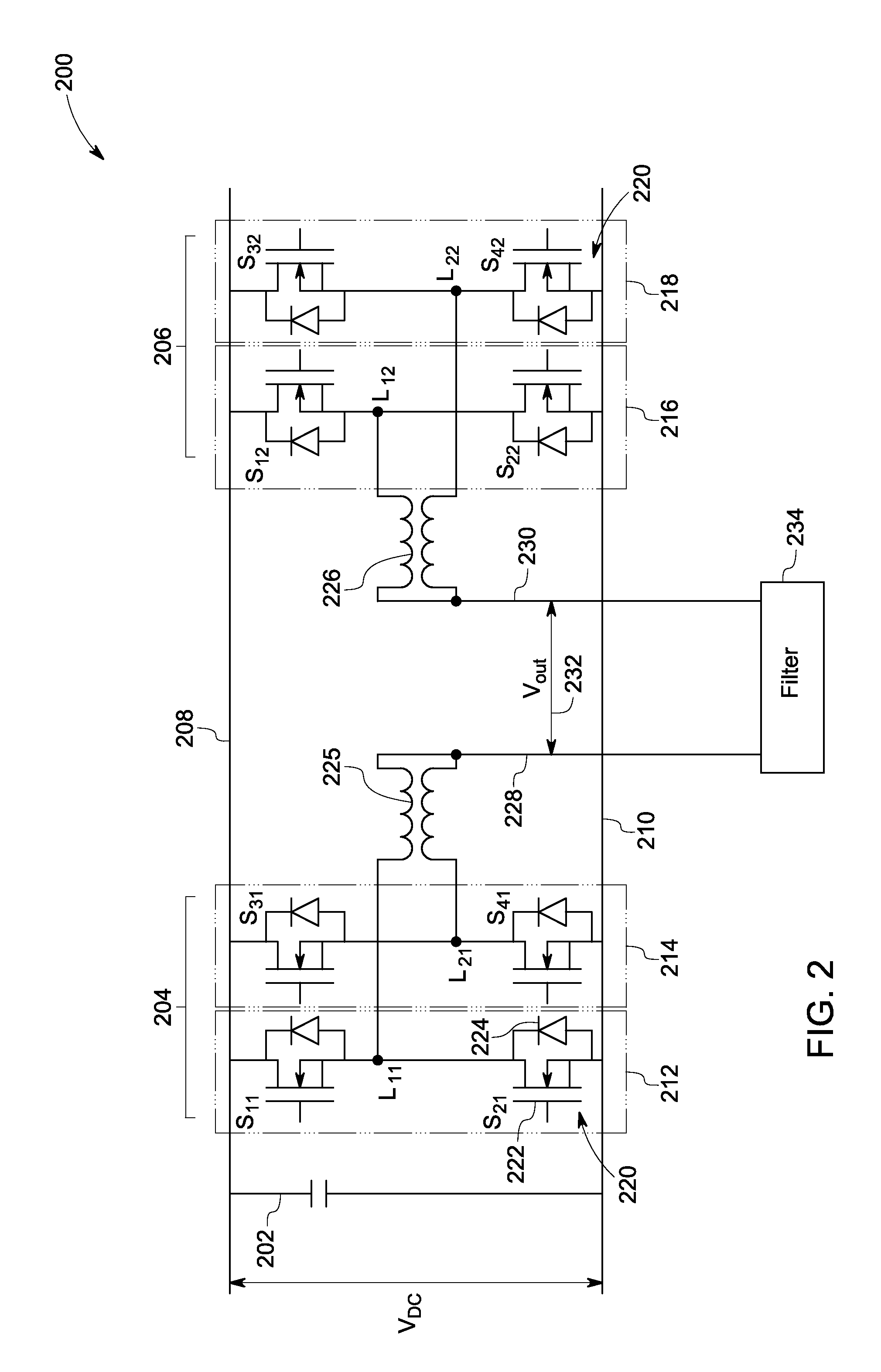
A power conversion system is presented. The power conversion system includes a power converter. The power converter includes at least two circuits, where each of the at least two circuits includes two or more phase legs, where each of the two or more phase legs includes at least two semiconductor switches. Also, the at least two circuits includes an interphase reactor configured to couple one of the two or more phase legs to at least one other phase leg in the two or more phase legs. Moreover, the power conversion system includes a controller configured to obtain a switching pattern for each of the at least two semiconductor switches of the at least two circuits and selectively switch each of the at least two semiconductor switches based on the obtained switching pattern to reduce a common mode signal in the power conversion system. Method for power conversion is also presented.

Description

[0001]This invention was made with Government support under grant number DE-EE0005344 awarded by the Government. The Government has certain rights in this invention.BACKGROUND[0002]Embodiments of the present disclosure generally relate to power conversion and more specifically to a power conversion system that includes a transformer-less inverter.[0003]As will be appreciated, an inverter is employed to convert a direct current (DC) to an alternating current (AC). Traditionally, inverters include transformers for providing galvanic isolation between a DC side and an AC side in order to prevent transmission of DC faults from the DC side to the AC side. The use of transformers in the inverters not only results in an increased footprint of the inverters, but also increases cost and lowers power conversion efficiency of the inverters. In recent times, there have been increased attempts to eliminate shortcomings associated with the use of transformer. To that end, different transformer-le...

Claims


Application Information

Patent Timeline
Patent Type & Authority Applications(United States)
IPC IPC(8): H02M7/5387H02M1/14
CPCH02M1/14H02M7/5387H02M7/493H02M1/123H02M1/0043
Inventor ZHOU, RUIGARCES, LUIS JOSETAO, FENGFENGTODOROVIC, MAJA HARFMANSTEPHENS, CHARLES MICHAELWANG, LEI
Owner GENERAL ELECTRIC CO
Learn More