Check patentability & draft patents in minutes with Patsnap Eureka AI!

Centrifugal microfluidic mixing apparatus and method

Active Publication Date: 2015-05-21
NAT RES COUNCIL OF CANADA
View PDF11 Cites 4 Cited by
  • Summary
  • Abstract
  • Description
  • Claims
  • Application Information

AI Technical Summary

Benefits of technology

This patent describes a centrifugal microfluidic device that can efficiently mix two or more fluids without the need for a separate mixing step. The device has a mixing chamber with fine flows of liquids that meet at a landing point on a mixing surface. The fluids flow through channels with different hydraulic diameters and create a mixing layer that is large enough for diffusion. The device can be made in any material that supports microfluidic circuitry, and can be operated with high fluid flow rates. The mixing is independent of the materials used and is almost instantaneous.

Problems solved by technology

This is a serious drawback for mixing two or more liquids since, in the absence of any turbulence, diffusive mixing is the only available mechanism.
This is an inherently very slow process.
As pointed out by these articles, while classical continuous microfluidics has been the field of several advancements and innovations in this matter, there is much on-going research and unsolved problems in centrifugal microfluidic mixing field.
The price to pay for this simple transfer of technology from traditional to centrifugal microfluidics is the complexity of both actuation and handling and the final fabrication cost per unit device.
These approaches are generally not appropriate for centrifugal microfluidic devices and do not take advantage of several features these platforms may offer.
However, this approach results in inefficient mixing.
As a consequence, the mixing time obtained is too long.

Method used


Image

  • Centrifugal microfluidic mixing apparatus and method
  • Centrifugal microfluidic mixing apparatus and method
  • Centrifugal microfluidic mixing apparatus and method

Examples


Embodiment Construction

[0031]The present invention comprises a microfluidic mixer in a microfluidic centrifugal device in which two or more liquid flows are efficiently mixed together in a mixing chamber.

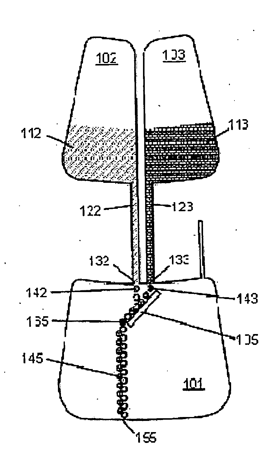
[0032]Referring to FIG. 1A, in a prior art microfluidic application (e.g. Burger 2009) where streams of liquid 12 and 13 flow simultaneously from reservoirs 2 and 3, respectively, to chamber 1, the flows arrive at inlets 32 and 33 from microfluidic channels 22 and 23, respectively, and the flow is fractionated into flows (streams of small droplets 42 and 43 shown), respectively. The size of these droplets is dictated by the strength of the centrifugal field, the capillary forces at the inlet and the geometry of the inlet. As the droplets are released at two different points (i.e.: inlets 32 and 33) they will be accelerated in the radial direction (i.e. in the direction of the centrifugal field) to land at two different points 52 and 53, respectively. Since these two points are relatively far from each oth...


PUM


Abstract

A centrifugal microfluidic device having a microfluidic mixing element with a microfluidic mixing chamber in which at least two flows emerging from channels into the chamber at separate places are redirected to land at substantially the same place on a mixing surface provides efficient mixing of two or more fluids in the chamber.

Description

CROSS-REFERENCE TO RELATED APPLICATIONS[0001]This application claims the benefit of U.S. Provisional Patent Application U.S. Ser. No. 61 / 599,647 filed Feb. 16, 2012, the entire contents of which is herein incorporated by reference.FIELD OF THE INVENTION[0002]The present invention is related to centrifugal microfluidic devices, in particular to centrifugal microfluidic devices having means for mixing fluids and to methods for mixing fluids in a centrifugal microfluidic device.BACKGROUND OF THE INVENTION[0003]Microfluidic devices are having an increasing impact on biomedical diagnostics and drug development. Centripetal (or centrifugal) microfluidics in particular can deal with very small volumes of liquid, usually in the microliter range. At such a small scale, the surface to volume ratio of flowing liquids increases drastically, while at the same time the specific Reynolds number becomes very small (typically less than 1). In such Reynolds number regimes the flow is always laminar, ...

Claims


Application Information

Patent Timeline
IPC IPC(8): B01F13/00B81B7/00
CPCB81B7/00B01F13/0059B01F25/4231B01F33/302B01F35/71725B01F33/30
Inventor CLIME, LIVIUVERES, TEODOR
Owner NAT RES COUNCIL OF CANADA
Features
  • R&D
  • Intellectual Property
  • Life Sciences
  • Materials
  • Tech Scout
  • Unparalleled Data Quality
  • Higher Quality Content
  • 60% Fewer Hallucinations
Learn More