
Redundant Network Implementation Method

a network implementation and redundancy network technology, applied in data switching networks, frequency-division multiplexes, instruments, etc., can solve the problems of network risk concentration, two protocols cannot meet the requirements of industrial networks in terms of real-time property, and relative long time for failure recovery, so as to reduce loop operation complexity and hardware requirements

Active Publication Date: 2015-05-21
KYLAND TECH CO LTD
View PDF5 Cites 18 Cited by
  • Summary
  • Abstract
  • Description
  • Claims
  • Application Information

AI Technical Summary

Benefits of technology

The present invention provides a method for implementing a redundant network that can select the best master station based on the quality of nodes. This reduces loop operation complexity and hardware requirements, while also ensuring link redundancy between networks. In summary, the technical effect of the invention is improved network efficiency and reliability.

Problems solved by technology

Although link failures may be detected by the two protocols, messages are frequently sent during operation to check the network state.
It could regularly cause a relatively long time for failure recovery.
As a result, the two protocols could not meet requirements of industrial networks in terms of real-time property.
There is a problem in the network risk concentration.
In addition, a redundancy protection on the kernel terminal equipment is not achieved.
Moreover, the EC 62439-3 PRP (Parallel Redundancy Protocol) uses two equivalently backbone networks, and a fast failure recovery for terminal equipment is realized using a dual-port redundancy technology, but there is a drawback of detecting well states of the dual ports and it results an increase in the system cost.
However, since the master stations take turns periodically, such requirements as complex loop operation and high hardware requirement should be met.

Method used


Image

  • Redundant Network Implementation Method
  • Redundant Network Implementation Method
  • Redundant Network Implementation Method

Examples


second embodiment

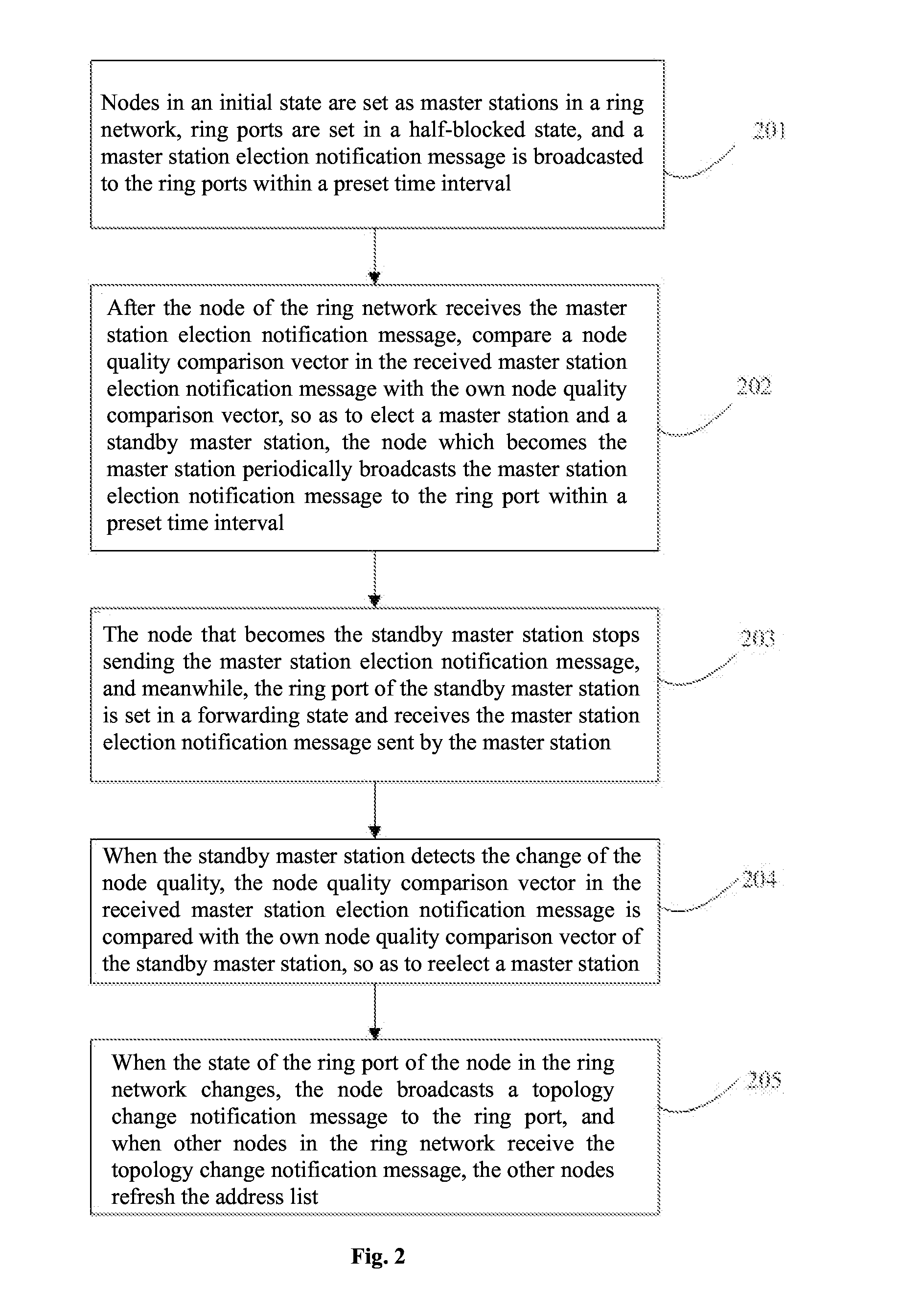
[0029]FIG. 2 shows a flowchart of implementation of master station redundancy in a single ring network according to the present invention. As shown in FIG. 2, the flow of implementing master station redundancy in the single ring network includes the following steps:

Step 201, all nodes in the ring network, when in the initial state, are assigned t as master stations. Additionally, the ring port of each node is set in the half-blocked state, and a master station election notification message is broadcasted to the ring ports within a preset time interval. The master station election notification message contains a node quality comparison vector. The node quality comparison vector has a link state identification, a CRC threshold-crossing level, an IP address and a Mac address. The link state identification is defined as a connection state, which is state of connection or disconnection between neighboring nodes. Also it has the priority demonstrating whether the node is elected to be as ...

third embodiment

[0034]A double ring network is formed when two single ring networks have two jointly-connected nodes and connecting links. The two jointly-connected nodes are shared nodes, and two links between the shared nodes are shared links One of the single ring networks is a primary ring network. The double ring network is a secondary ring network, and the shared nodes can be elected as the master station and the standby master station of the secondary ring network. The primary ring network and the secondary ring network are divided into different ring network domains according to different IDs by a user. The primary ring network can implement an election of the master station and the standby master station according to the steps of the single ring network. The primary ring network manages the state of the ring ports of the primary ring network, and it is capable of transferring the protocol message of the secondary ring network. The shared nodes can participate in the election of the master ...

fourth embodiment

[0035]FIG. 4 is a structure diagram of a double ring network in the present invention. As shown in FIG. 4, a double ring network is established when a single ring network 1 and a single ring network 2 have jointly-connected node A and node B and connecting links. The node A and the node B are shared nodes. Two links between the node A and the node B composed of a primary ring network are shared links of the secondary ring network The links between the node A, the node B, a node 11 and a node 12 in the primary ring network or links between the node A and the node B are regarded as the shared links of the secondary ring network. The primary ring network includes the node 11, the node 12, the node A and the node B, and the nodes are mutually connected through links. Moreover, the secondary ring network includes a node 21, a node 22, the node 11, the node 12, the node A and the node B, and the nodes are mutually connected through links. The shared nodes can be elected as the master stat...


PUM


Abstract

Disclosed is a method of implementing a redundant network. Ring network nodes in an initial state are set as master stations, ring ports are set in a half-blocked state, a master station election notification message is broadcast to the ring ports within a preset time interval, the nodes receive the master station election notification message, a node quality comparison vector is compared with node quality comparison vectors of the nodes to elect a master and standby stations, one of the ring ports is in the half-blocked state, the other ring ports are in a forwarding state, the master station broadcasts the master station election notification message to the ring ports, the standby master station stops sending the master station election notification message, the ring ports are in the forwarding state, and the message sent by the master station is received.

Description

FIELD OF THE INVENTION[0001]The present invention relates to the technical field of ring network, and in particular to a redundant network implementation method.BACKGROUND OF THE INVENTION[0002]In order to overcome redundancy on a network transmission path, a rapid spanning tree protocol (RSTP, see IEEE802.1w) and a multiple spanning tree protocol (MSTP, see IEEE802.1w) are adopted in the current high-availability network. These two protocols are applicable to a ring network to achieve path redundancy through certain algorithms, and to prune the ring network into a loop-free tree network at the same time.[0003]Although link failures may be detected by the two protocols, messages are frequently sent during operation to check the network state. It could regularly cause a relatively long time for failure recovery. As a result, the two protocols could not meet requirements of industrial networks in terms of real-time property.[0004]To meet the requirements of network protocols on the re...

Claims


Application Information

Patent Timeline
Patent Type & Authority Applications(United States)
IPC IPC(8): H04L12/24
CPCH04L41/0654H04L1/22H04L12/42H04L12/427H04L1/0061
Inventor MA, HUAYIXUE, BAIHUAJIANG, QIYUNHE, YINGJUNCHEN, FANMINHUANG, JIANCHAOZHANG, JIANFENGZHAO, SHUCHANG
Owner KYLAND TECH CO LTD
Learn More