Satellite positioning system

a satellite positioning system and positioning system technology, applied in the field of satellite positioning systems, can solve the problems of reducing the processing and hardware requirements of existing satellite positioning systems, and achieve the effect of reducing processing and hardware requirements

Inactive Publication Date: 2005-09-27
GENERAL DYNAMICS C4 SYSTEMS
View PDF16 Cites 10 Cited by
  • Summary
  • Abstract
  • Description
  • Claims
  • Application Information

AI Technical Summary

Benefits of technology

[0011]In embodiments of the present invention, mobile monitoring stations may be used in addition to or instead of stationary stations in situations where stationary stations are impractical or undesirable. Furthermore, because the positioning effect of the methods disclosed in present invention are so stable, the single data correction satellite upload needed for the entire constellation may only be needed once every two days or once every week. This significantly reduces the processing and hardware requirements of existing satellite positioning systems. In a particular embodiment of the invention, the satellite constellation is configured as a global positioning system (GPS). The present invention also contemplates additional satellites, independent or within another constellation, temporarily and passively accessing a satellite within a constellation configured according to the present invention, determining its own relative positioning and clock and applying the constellation solution to itself to update its own clock and positioning data.

Problems solved by technology

This significantly reduces the processing and hardware requirements of existing satellite positioning systems.

Method used


Image

  • Satellite positioning system
  • Satellite positioning system
  • Satellite positioning system

Examples


Embodiment Construction

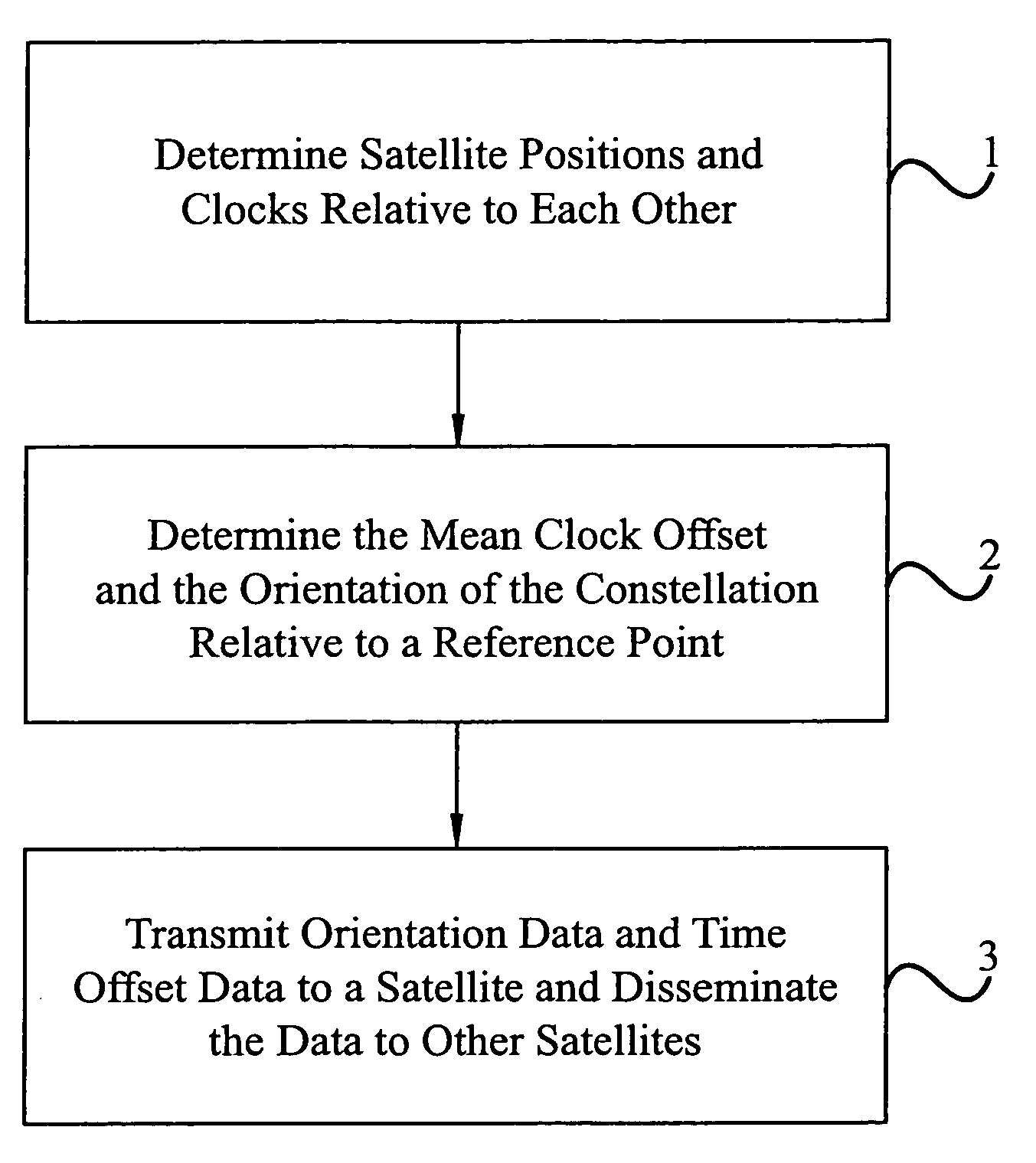
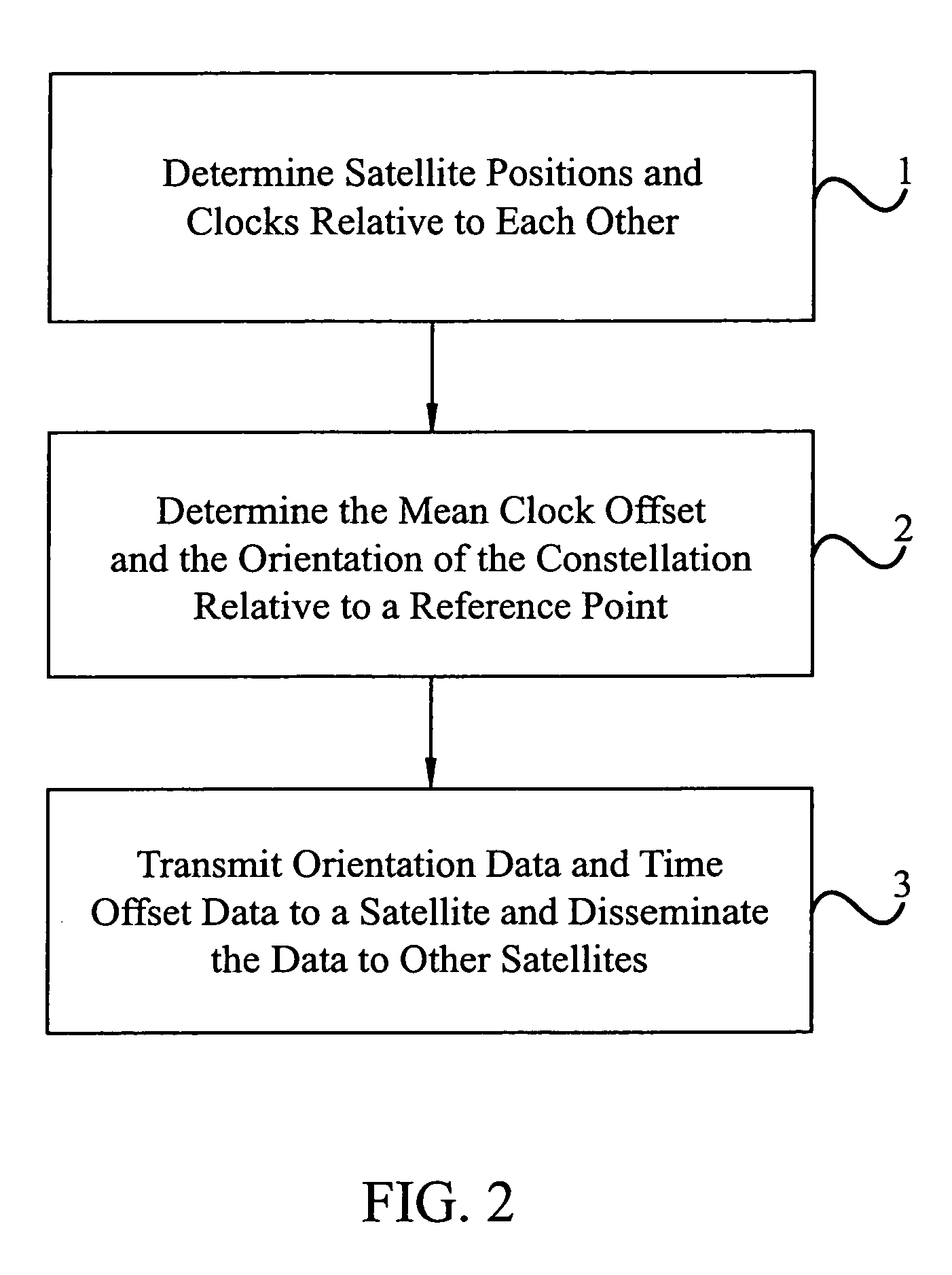
[0023]FIG. 2 includes a flow diagram of a method of determining an orbital position of a satellite in a constellation and of synchronizing the clocks of the satellites in the constellation. The method includes primarily three steps which are: 1) Determine the positions and clocks of each of the satellites in the constellation relative to the other satellites in the constellation (step 1); 2) Determine the orientation of the constellation relative to the Earth, and determine the mean clock offset of the satellites in the constellation (step 2); and 3) Transmit orientation data and time offset data to a satellite in the constellation and disseminate the data to the other satellites in the constellation. As used herein, the term “orientation data” is intended to include all forms of data relating to associations between two or more calculated, measured or actual positions such as, but not limited to, distances, coordinate locations, angles, vectors, and any value or data relating to or...


PUM


Abstract

A satellite positioning system and method of maintaining the positioning and clock data of a satellite using as few as one or two monitoring stations is disclosed. Each satellite of the positioning system determines its own positioning and clock data relative to other satellites in a constellation. One or more satellite signal monitoring stations receive relative clock and positioning data from a plurality of satellites in the constellation. A constellation solution which is applicable to all of the satellites in the constellation is calculated by treating the constellation as a rigid body at a fixed point in time. The constellation solution is transmitted to a satellite of the constellation which disseminates the solution through a crosslink network within the constellation for use by each satellite to update its individual positioning and clock data as needed. Due to the stability of the position and clock measurements using the method of the present invention, satellite uploads need only occur for one satellite in a constellation once each two or more days rather than every day for every satellite as is conventionally done. The use of mobile monitoring stations and the capacity of the positioning system to assist in updating the position and clock data of satellites passing the constellation are disclosed. In particular embodiments of the invention, the satellite positioning system is configured as a global positioning system (GPS).

Description

BACKGROUND OF THE INVENTION[0001]1. Technical Field[0002]This invention generally relates to satellite systems, and more specifically to a satellite orbit monitoring system which determines and maintains accurate satellite orbit data using as few as one or two ground stations. The invention also relates to providing a common satellite position and time correction data update signal applicable to all satellites in a constellation.[0003]2. Background Art[0004]A Global Positioning System (GPS) is a space-based radio positioning network designed to provide users who are equipped with a suitable receiver with position, velocity, and time (PVT) information. Developed by the United States Department of Defense (DOD), the space-based portion of GPS comprises a constellation of GPS satellites in non-geosynchronous 12 hour orbits around the Earth.[0005]FIG. 1 shows an exemplary constellation 100 of GPS satellites 101 in orbit around the Earth. The GPS satellites 101 are located in six orbital...

Claims


Application Information

Patent Timeline
Patent Type & Authority Patents(United States)
IPC IPC(8): H04B7/185B64G1/10B64G1/24G01S1/00
CPCB64G1/1085B64G1/242G01S19/02
Inventor KLEIN, DALE W.
Owner GENERAL DYNAMICS C4 SYSTEMS
Why Eureka
Try Eureka