Calibration method for multi-component force detector provided in rolling resistance testing machine

a multi-component force detector and rolling resistance testing technology, which is applied in vehicle tyre testing, instrumentation, weighing auxiliaries, etc., can solve the problems of difficult to calibrate a crosstalk correction coefficient with high accuracy, the calibration test itself is not satisfactorily, and the method is not practical, so as to achieve accurate calibration and easy and accurate

Active Publication Date: 2015-05-28
KOBE STEEL LTD
View PDF7 Cites 7 Cited by
  • Summary
  • Abstract
  • Description
  • Claims
  • Application Information

AI Technical Summary

Benefits of technology

[0015]The present invention has been made keeping in mind the above problems, and an object of the present invention is to provide a calibration method capable of calibrating a crosstalk correction coefficient of a multi-component force detector provided in a rolling resistance testing machine with ease and high accuracy.
[0018]The inventors thought that, when the reference tire whose rolling resistance value is known is tested in the situation that the measurement value of the multi-component force detector is calibrated with satisfactory precision in an axial direction thereof, there is a difference between the measuring result of the multi-component force detector and the rolling resistance value of the reference tire, and such a difference is mainly attributed to the influence of crosstalk caused by the action of other loads. Accordingly, the inventors found that, if the crosstalk correction coefficient was calibrated by equalizing both of the rolling resistances, easy and highly accurate calibration was possible, and completed the present invention.
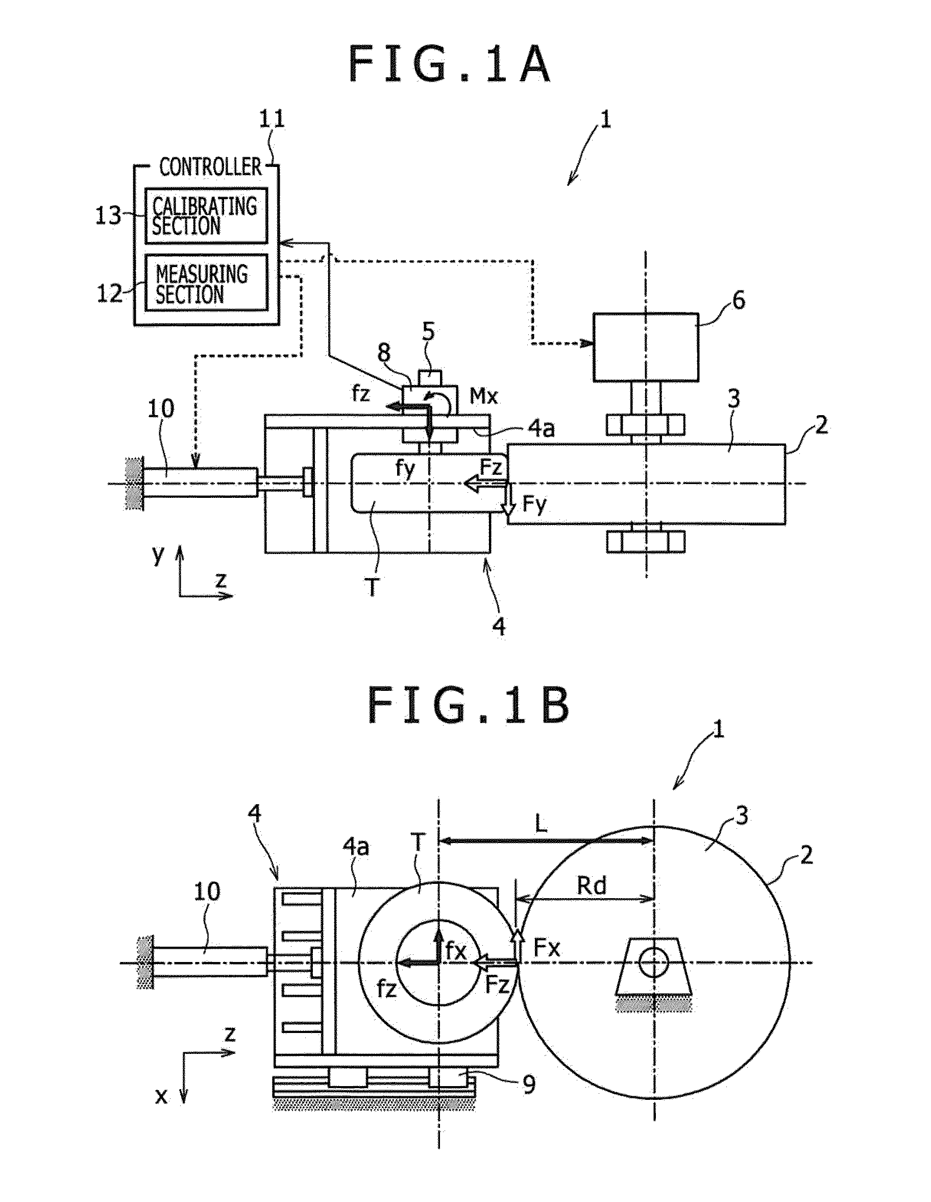
[0022]The force fz acting in the z-axial direction and the moment mx around the x axis easily exerts an influence of crosstalk on the moment fx around the x axis among loads and moments measured by the multi-component force detector. Accordingly, with respect to the multi-component force detector that can at least detect the force fx acting in the x-axial direction, the force fz acting in the z-axial direction, and the moment mx around the x axis, the crosstalk correction coefficients of the force fz acting in the z-axial direction and the moment mx around the x axis relative to the force fx acting in the x-axial direction may be calibrated.
[0026]With respect to the multi-component force detector that can measure all of the force fx acting in the x-axial direction, the force fz acting in the z-axial direction, the force fy acting in the y-axial direction, and the moment mx around the x axis, all of the crosstalk correction coefficients of the force fz acting in the z-axial direction, the force fy acting in the y-axial direction, and the moment mx around the x axis relative to the force fx acting in the x-axial direction are calibrated. Thereby, more highly accurate calibration of the multi-component force detector is possible.
[0028]A considerable influence of rotational friction is present at the bearings provided for the rotary shaft of a spindle or a rotary drum mounting the tire. When the rotational friction is added to the measurement value of a rolling resistance force, it is difficult to measure fx or to calibrate the crosstalk correction coefficient with precision. Thus, if the crosstalk correction coefficient is calibrated using the differential load obtained by subtracting a state in which a load (for instance, a skim load) different from the test load is applied from a state in which the test load is applied, the calibration can be performed while excluding the influence of rotational friction, and the crosstalk correction coefficient can be accurately calibrated.
[0029]According to the calibration method for the multi-component force detector provided for the rolling resistance testing machine of the present invention, the crosstalk correction coefficient of the multi-component force detector provided for the rolling resistance testing machine can be calibrated in an easy and accurate way.

Problems solved by technology

Especially, in the multi-component force detector provided for the rolling resistance testing machine, the crosstalk, for instance, by which the pressing load has an influence on a rolling load becomes an issue.
Further, if a direction in which the axial load (pressing load) deviates even slightly, test conditions are changed, and a calibration test itself is not satisfactorily made.
Of course, on the test conditions that are not properly determined in this way, it is also difficult to calibrate a crosstalk correction coefficient with high accuracy.
However, this method is not practical because there is a need for a calibration test that provides Fy and Fz as well as Mx, My, and Mz in addition to Fx as the values given to the multi-component force detector, and it takes labor.

Method used


Image

  • Calibration method for multi-component force detector provided in rolling resistance testing machine
  • Calibration method for multi-component force detector provided in rolling resistance testing machine
  • Calibration method for multi-component force detector provided in rolling resistance testing machine

Examples


first embodiment

[0053]First, a calibration method for a multi-component force detector of a first embodiment will be described.

[0054]The calibration method of the first embodiment is employed in the case of using the multi-component force detector capable of measuring fx, fz, and mx.

[0055]A crosstalk correction coefficient a of the axial load fz relative to fx and a crosstalk correction coefficient b of mx relative to fx are calibrated in the following order.

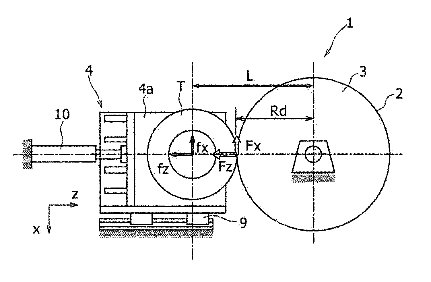
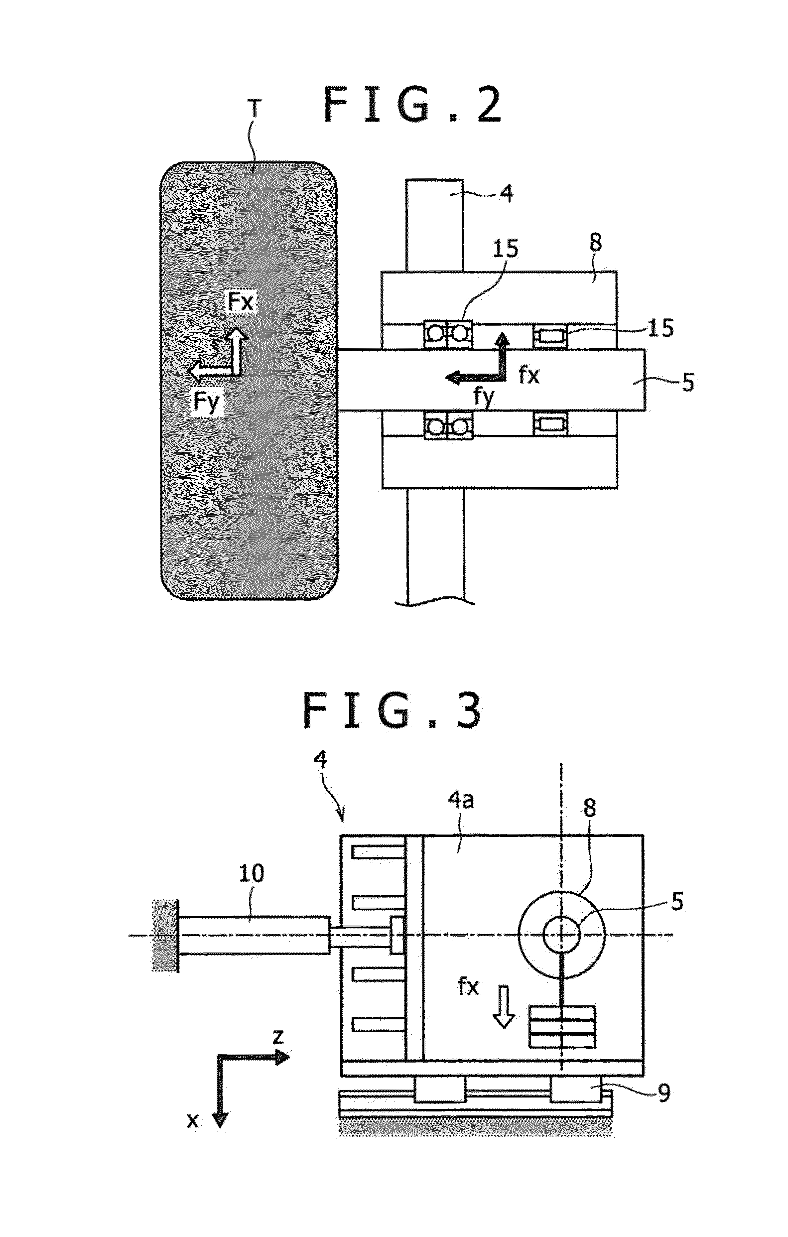
[0056]First, as illustrated in FIG. 3, calibration is performed by mounting a weight whose mass is known on the spindle 5, applying a load in an x direction, and measuring a load applied in the same direction by the multi-component force detector. In this way, a calibration coefficient α of a measurement value fx′ of the multi-component force detector relative to fx can be obtained.

[0057]Further, as illustrated in FIG. 4, a high-precision load tester 14 is installed between the spindle 5 and the traveling drum 3, and the carriage 4 is displaced...

second embodiment

[0070]Next, a calibration method for a multi-component force detector of a second embodiment will be described.

[0071]Unlike the first embodiment, the calibration method of the second embodiment is to use the multi-component force detector capable of measuring fx, fz, and fy, and to calibrate crosstalk correction coefficients a and c of fz′ and fy′, respectively relative to fx.

[0072]The crosstalk correction coefficients a and c of the second embodiment are calibrated in the following order.

[0073]First, as illustrated in FIG. 3, similar to the first embodiment, a calibration coefficient α is obtained, which is included in a measurement value fx′ measured with respect to fx in a rolling resistance direction.

[0074]Next, when the crosstalk influence of fy′ in place of mx′ is taken into account, a force fx of the rolling resistance direction is represented as in formula (3). In formula (3), c is a crosstalk correction coefficient caused by a y-directional measurement value fy′.

fx=α·fx′+a·...

third embodiment

[0082]Next, a calibration method for a multi-component force detector of a third embodiment will be described.

[0083]Unlike the first and second embodiments, the calibration method of the third embodiment is to use the multi-component force detector capable of measuring all of fx, fz, fy, and mx, and to calibrate all of the aforementioned crosstalk correction coefficients a, b and c.

[0084]The crosstalk correction coefficients a, b and c of the third embodiment are calibrated in the following order.

[0085]First, similar to the first and second embodiments, as illustrated in FIG. 3, a calibration coefficient α of a measurement value fx′ relative to fx in a rolling resistance direction is obtained.

[0086]Taking into consideration the calibration coefficient α and the crosstalk correction coefficients a, b and c, fx of the present embodiment is represented as in formula (5).

fx=α·fx′+a·fz′+b·mx′+c·fy′  (5)

[0087]Meanwhile, fx is calculated by formula (2) based on a rolling resistance coeffic...


PUM

PropertyMeasurementUnit
rolling resistanceaaaaaaaaaa
rolling resistance valueaaaaaaaaaa
rolling resistance testing machineaaaaaaaaaa

Abstract

The calibration method for a multi-component force detector is a calibration method for a multi-component force detector provided in a rolling resistance testing machine comprising a spindle to which a tire is mounted, and a traveling drum having a simulated traveling road surface against which the tire is pressed, wherein when processing for calculating force acting on the tire from the measurement value of the multi-component force detector using a crosstalk correction factor for correcting the influence of crosstalk occurring in the multi-component force detector is performed, a test is conducted using at least one or more reference tire the rolling resistance value of which is already known, and the crosstalk correction factor is calibrated using “rolling test data” composed of force measured by the multi-component force detector during the test using the reference tire, and the rolling resistance value of the reference tire used for the measurement.

Description

TECHNICAL FIELD[0001]The present invention relates to a calibration method for a multi-component force detector provided in a rolling resistance testing machine.BACKGROUND ART[0002]When the nature and performance of tires for trucks, passenger cars, and other vehicles are measured, one of important measurement items is rolling resistance of the tire. The rolling resistance of the tire is a tangential force acting between the tire and the ground. In a rolling resistance testing machine, the rolling resistance is measured as a force Fx (a change in rolling resistance Fx when a pressing load Fz is changed) that acts between a testing tire and a simulated traveling road surface such as a drum in a tangential direction.[0003]A method based on a drum type rolling resistance testing machine is representative of a method of measuring the rolling resistance Fx. The drum type rolling resistance testing machine is configured to bring a tire into contact with a simulated traveling road surface ...

Claims


Application Information

Patent Timeline
Patent Type & Authority Applications(United States)
IPC IPC(8): G01L25/00G01M17/02
CPCG01M17/02G01L25/00G01M17/022
Inventor OKADA, TORUFUKUDA, TAKAYUKISUMITANI, TAKASHI
Owner KOBE STEEL LTD
Why Eureka
Try Eureka