

Ignition device
a technology of ignition device and ignition plug, which is applied in the direction of spark plugs, machines/engines, mechanical equipment, etc., can solve the problems of unstable ignition, difficult ignition of high-efficiency engines by sparking, etc., and achieve the effect of stable ignition and high electrical conductivity
- Summary
- Abstract
- Description
- Claims
- Application Information
AI Technical Summary
Benefits of technology
Problems solved by technology
Method used
Image

Examples
Embodiment Construction
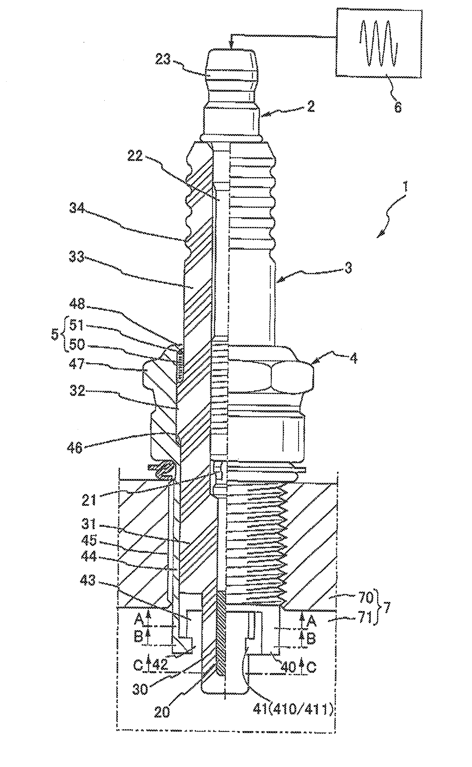
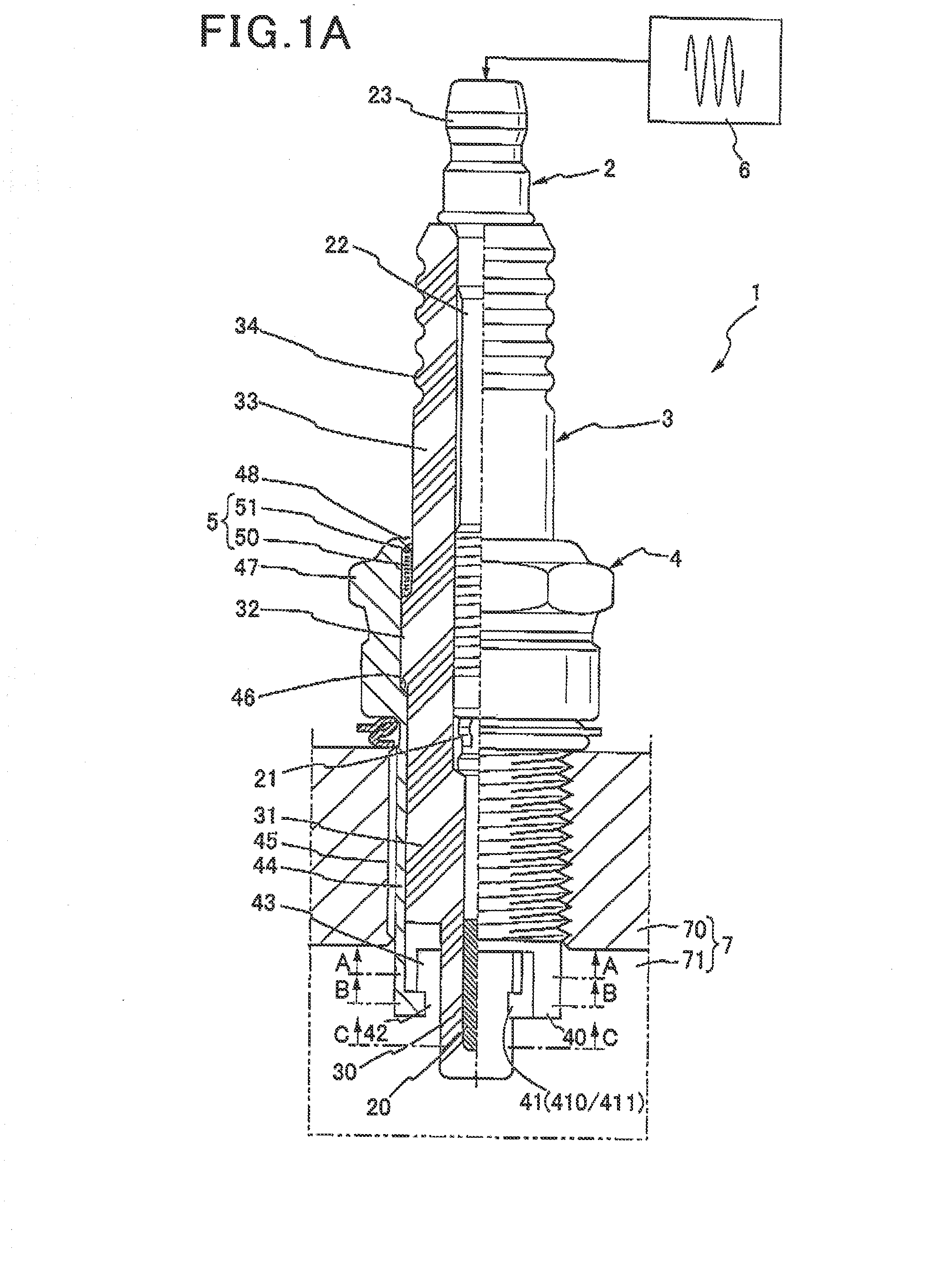
[0055]An ignition device 1 according to a first embodiment of the invention is described with reference to FIGS. 1A, 1B, 1C and 1D. The ignition device 1 is a device for igniting an air-fuel mixture introduced into a combustion chamber 71 of an internal combustion engine 7. The ignition device 1 is mounted on an engine block 70 of the internal combustion engine 7 such that its distal end is exposed to the inside of the combustion chamber 71.
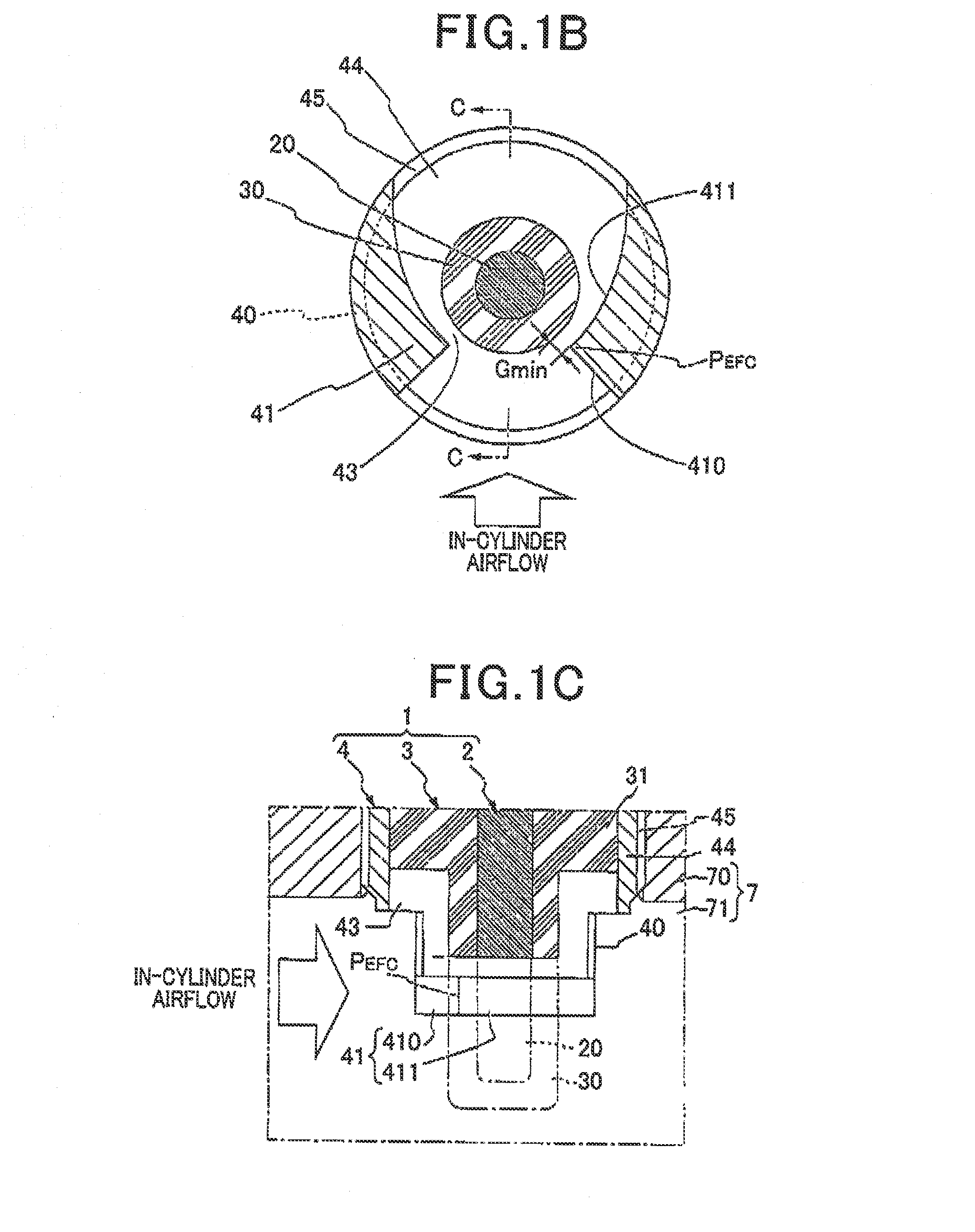
[0056]The ignition device 1 includes a columnar center electrode 2, a center dielectric 3 having a shape of a bottomed cylinder covering the center electrode 2, a tubular housing 4 housing therein the center dielectric 3, a ground electrode 40 disposed at the distal end of the housing 4 so as to form a discharge space 43 with the center dielectric 3, and a high energy power source 6 for applying a high AC voltage of a predetermined frequency between the center electrode 2 and the ground electrode 40. The high energy power source 6 forms a high fr...
PUM
 Abstract
Description
Claims
Application Information