Modular installation for the manufacture of an explosive emulsion precursor

a technology of explosive emulsion and module installation, which is applied in the direction of explosives, dissolving with driven stirrers, lighting and heating apparatus, etc. it can solve the problems of insufficient stability of premix, inability to meet the needs of production, so as to increase the viscosity of emulsion, facilitate sampling, and reduce the effect of cos

Active Publication Date: 2015-05-28
INNOVATION & IND
View PDF4 Cites 3 Cited by
  • Summary
  • Abstract
  • Description
  • Claims
  • Application Information

AI Technical Summary

Benefits of technology

[0023]capable of being assembled readily on-site without the need for too many hours of work on specific skills; and
[0102]In addition, the quantity of emulsion present in the tank for preparing the emulsion is a minimum, and so the safety of the installation is improved.

Problems solved by technology

Because of its low viscosity, this premix has insufficient stability and its consistency is not appropriate for its subsequent use in preparing the explosive.
Firstly, those small installations have small production capacity, and secondly they are relatively dangerous because oxidant (aqueous phase) and fuel (oily phase) are transported close to each other with no safe physical separation of the tanks.
That results in a method and a device that are relatively complex and expensive to implement.
The fact that the three steps in preparing the emulsion occur in the same container gives rise to risks as regards the safety of the site and / or of operators in the event of an incident and / or damage.
In addition, transporting containers of such a large size is not easy.
It is in fact desirable to be able to transport containers that have already been fitted out, because if the installation is assembled on site, it requires qualified personnel to be mobilized, which gives rise to additional costs, in particular if optional elements are to be added subsequently.

Method used


Image

  • Modular installation for the manufacture of an explosive emulsion precursor
  • Modular installation for the manufacture of an explosive emulsion precursor
  • Modular installation for the manufacture of an explosive emulsion precursor

Examples


Embodiment Construction

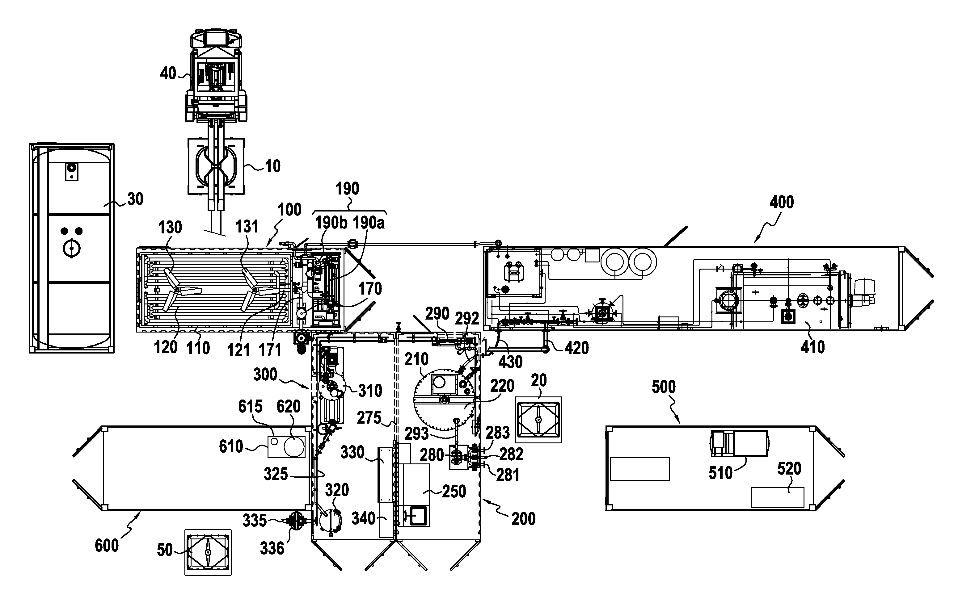
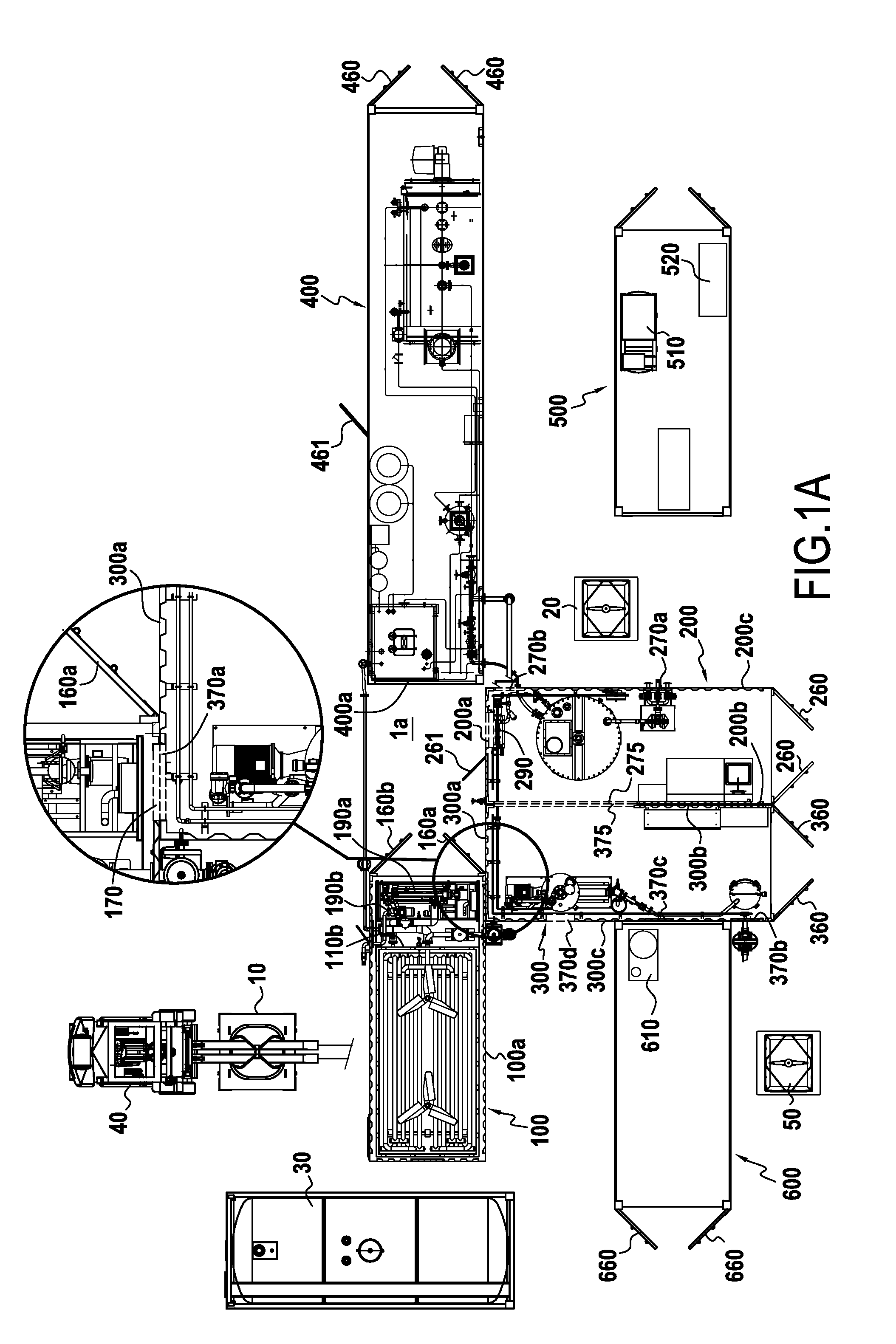
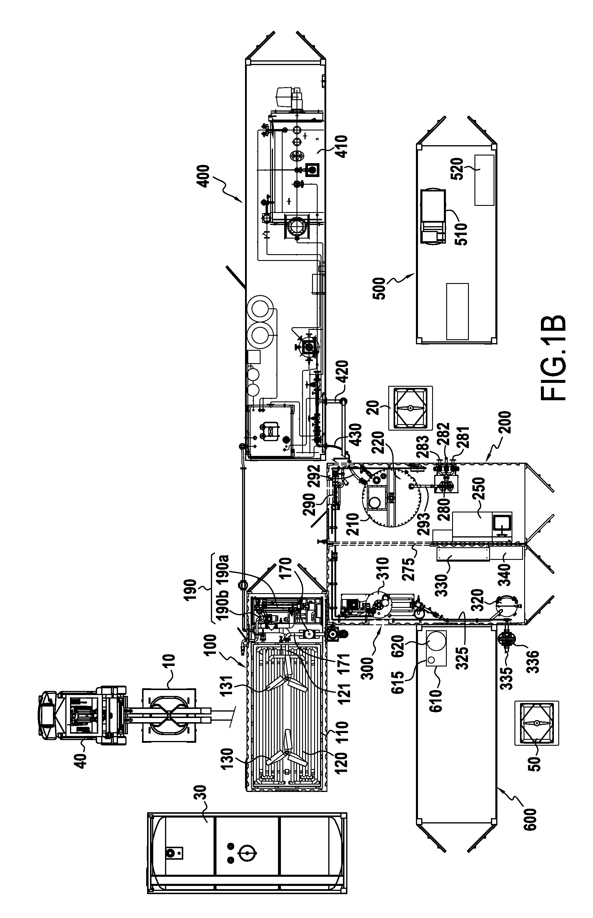
[0122]The modular installation 1 comprises a first container 100 for preparing an aqueous phase, a second container 200 for preparing an oily phase, and a third container 300 for preparing a reverse emulsion by mixing the aqueous phase and oily phase. Each of the first, second, and third containers 100, 200, and 300 is equipped with first, second, and third tanks 110, 210, 310 for preparing the aqueous phase for the first tank 110, the oily phase for the second tank 210, and the emulsion by mixing the aqueous phase and oily phase incorporating a surfactant for the third tank 310. These three containers also contain pumping means 190a, 190b, 280, 290, 305, and 336 for routing the fluids concerned via fluid transfer lines into or towards the various tanks, as is described below.

[0123]FIG. 1 also shows a fourth container 400 including means for feeding heat transfer fluid, more particularly a heater 410 producing steam, and a fifth container 500 including means for producing electricit...


PUM

PropertyMeasurementUnit
temperatureaaaaaaaaaa

Abstract

The present invention provides a modular installation (1) for carrying out a method of manufacturing an explosive emulsion precursor comprising at least three containers: —a first container (100) for preparing an aqueous phase, including a dissolution first tank (110); and —at least one second and / or third container (200, 300) including a second tank for preparing oily phase (210) and a third tank for preparing emulsion (310); and —at least one fourth and / or fifth container (400, 500) including means (410) for feeding heat and means (510) for feeding electrical energy; and —said first, second and / or third containers (100, 200, 300) being juxtaposed over at least a portion of one of their walls (100a, 300b, 200b) and being provided with openings (170, 370a, 275, 375, 270b) in their walls.

Description

BACKGROUND OF THE INVENTION[0001]The present invention relates to an installation and to a method for on-site preparation of a precursor of an explosive emulsion constituted by a reverse emulsion (water-in-oil).[0002]In order to limit risks linked to transport, explosive precursors are manufactured on-site by emulsifying a concentrated aqueous phase, in particular supersaturated with nitrates constituting an oxidant, in an oily phase containing a surfactant and constituting a mixture of fuels.[0003]The aqueous phase is typically prepared by dissolving nitrates of ammonium and / or sodium and / or calcium in water, to which there are additives for encouraging gasification and additives for adjusting the pH of the aqueous phase. Because of the high concentration of nitrates (in a proportion by weight of approximately 80%-82% for 18%-20% of water) and in order to facilitate dissolving them, the water is heated to a temperature of at least 65° C. (degrees Celsius).[0004]The oily phase is co...

Claims


Application Information

Patent Timeline
Patent Type & Authority Applications(United States)
IPC IPC(8): C06B47/14B01F15/06B01F3/08C06B31/00C06B21/00
CPCC06B47/14C06B31/00B01F2015/062B01F3/0815B01F15/06C06B21/0008C06B47/145F28F13/125F28D1/0213F28D7/024F28D7/087B01F21/10B01F27/192B01F27/85B01F27/90B01F35/93B01F2035/99B01F33/5013B01F23/411B01F35/90
Inventor EATON, JAMES C.JAUFFRET, GILLES
Owner INNOVATION & IND
Why Eureka
Try Eureka