Shock-absorber and method for manufacturing a shock-absorber

a technology of shock absorption and shock absorption tube, which is applied in the field of shock absorption tube and manufacturing method, can solve the problems of deformation of the base body of rubber and tendency to become longer, and achieve the effects of reducing total rigidity, reducing and preventing excessive increase in the density or total volume of the shock absorption tub

Inactive Publication Date: 2015-05-28
CIKAUTXO
View PDF10 Cites 2 Cited by
  • Summary
  • Abstract
  • Description
  • Claims
  • Application Information

AI Technical Summary

Benefits of technology

[0007]Vibration transmission from the first component, such as a vehicle exhaust pipe, to the second component, such as a vehicle frame, is significantly reduced by the shock absorber in a simple, economical and effective manner, it not being necessary to provide the shock-absorber with complex shapes for reducing the total rigidity. At the same time, an excessive increase in the density or total volume of the shock-absorber is prevented, which would be counterproductive for minimizing vibration transmission.
[0008]Additionally, assembling operations in assembly lines are also made easier because at least the first component is inserted in a non-rigid area, which makes the operation of inserting the first component into the first area easier.

Problems solved by technology

However, the greater the rigidity of the shock-absorber the lower the vibration damping power, i.e., the more rigid the shock-absorber is, the more vibrations it will transmit.
When the shock-absorber is subjected to static and dynamic loads, the base body made of rubber is deformed, tending to become longer.

Method used


Image

  • Shock-absorber and method for manufacturing a shock-absorber
  • Shock-absorber and method for manufacturing a shock-absorber
  • Shock-absorber and method for manufacturing a shock-absorber

Examples


Embodiment Construction

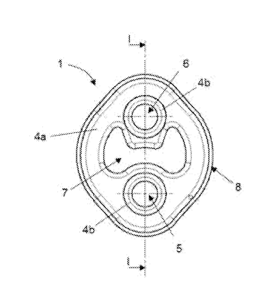
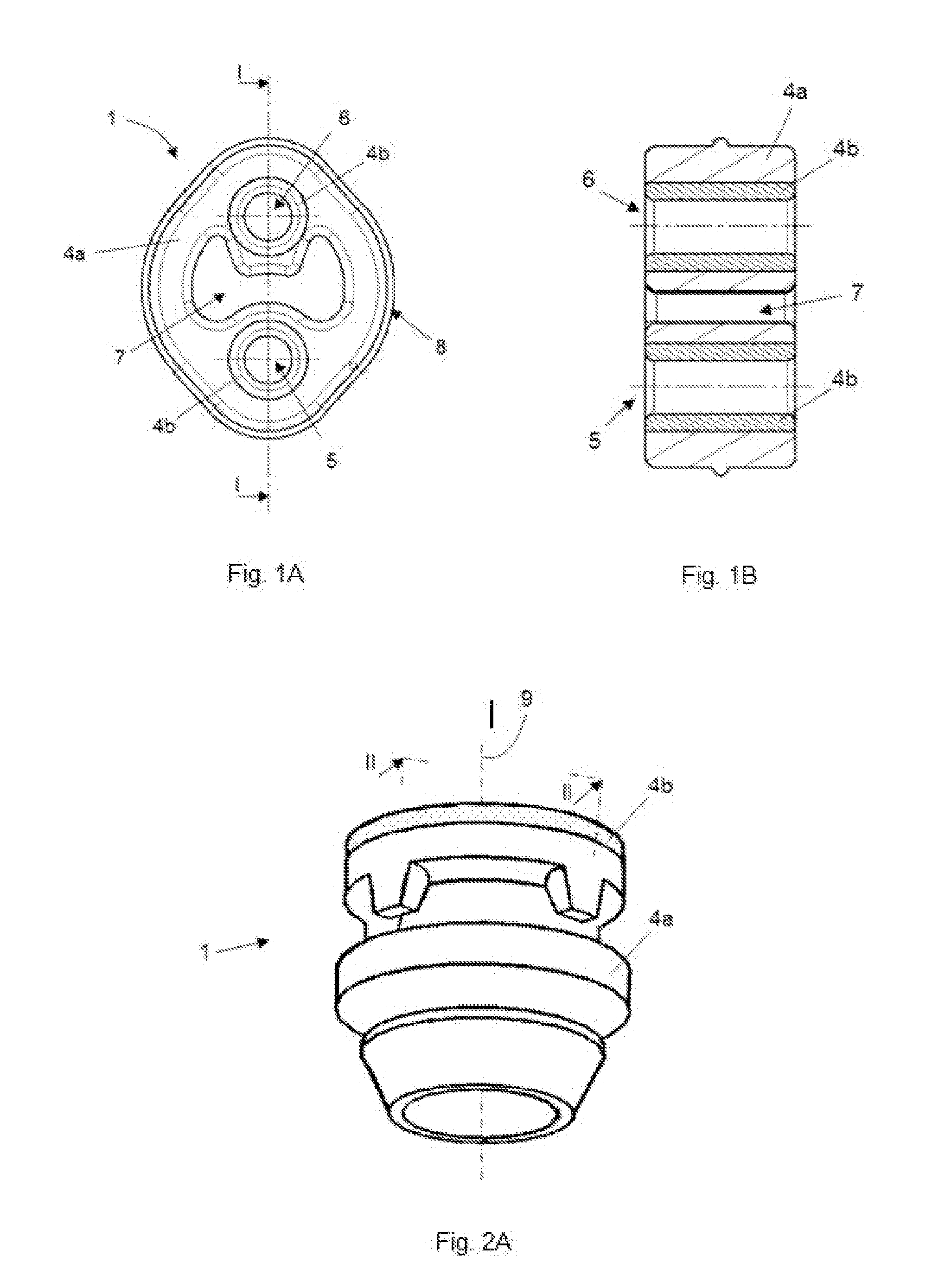
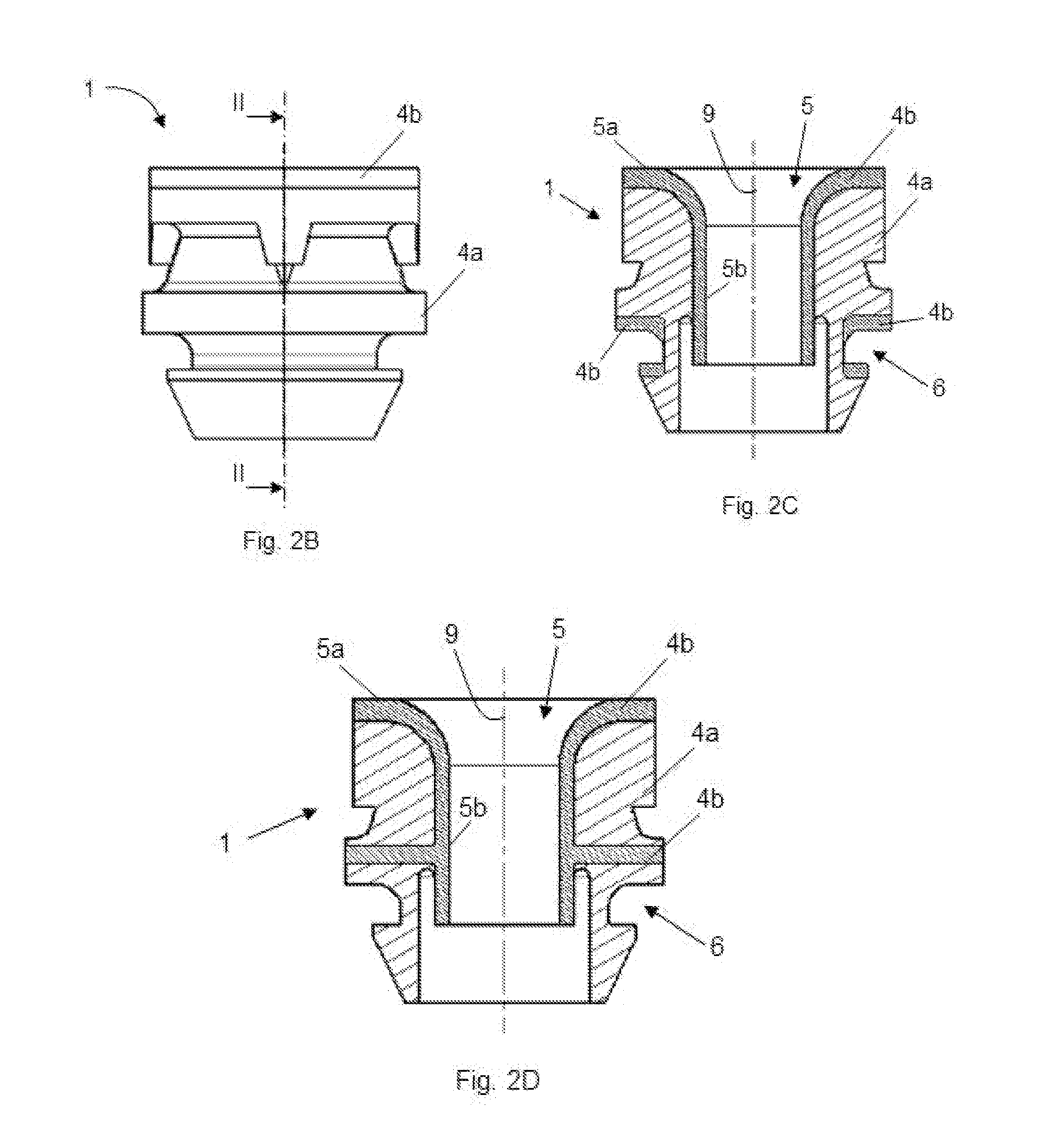
[0017]According to the implementations disclosed herein, a shock-absorber 1 is provided that is suitable for joining a first component 2 subjected to vibrations to a second, preferably static, component 3. The shock-absorber 1 includes a first area 5 which is designed for being joined to the first component 2 and a second area 6 designed for being joined to the second component 3. The shock-absorber 1 also includes a first elastic material 4a covering a large part / majority of the volume of the shock-absorber 1 and a second also elastic material 4b but of a lower density located at least in the first area 5. The second material 4b at least partially contacts the first component 2.

[0018]The first material 4a comprises a density and geometry that provides the shock-absorber 1 with sufficient rigidity so that it can withstand the static loads to which it is subjected without exceeding its elastic limit. This material, as seen in the drawings, covers a majority of the volume of the shock...


PUM

PropertyMeasurementUnit
densityaaaaaaaaaa
densityaaaaaaaaaa
densitiesaaaaaaaaaa

Abstract

A shock-absorber suitable for joining a first component subjected to vibrations, such as a vehicle exhaust pipe, to a second component, such as a vehicle frame, and a method for manufacturing the shock-absorber. According to some implementations the shock-absorber is made of a first elastic material of a first density constituting a majority of the volume of the shock-absorber and a second elastic material of a second density less than the first density. The shock absorber includes a first area designed for being joined to the first component and a second area designed for being joined to the second component. The second elastic material at least partially covers the first area and is configured to at least partially contact the first component when the first component is assembled within the first area.

Description

CROSS-REFERENCE TO RELATED APPLICATIONS[0001]This application relates to and claims the benefit and priority to Spanish Patent Application No. P201331710, filed Nov. 22, 2013.TECHNICAL FIELD[0002]The disclosure relates to shock-absorbers capable of joining a first component subjected to vibrations to a second component. The disclosure also relates to the method for manufacturing the shock-absorbers.BACKGROUND[0003]Shock-absorbers capable of joining a first component subjected to vibrations, such as a vehicle exhaust pipe, for example, to a second component, such as a vehicle frame, for example, are known. These shock-absorbers are usually made of rubber and must be rigid enough to withstand the static loads to which it is subjected, such as the weight of the first component, for example, which usually hangs from the shock-absorber. However, the greater the rigidity of the shock-absorber the lower the vibration damping power, i.e., the more rigid the shock-absorber is, the more vibra...

Claims


Application Information

Patent Timeline
Patent Type & Authority Applications(United States)
IPC IPC(8): F16F3/093B29C70/68
CPCF16F3/093B29C70/68B29L2031/721B29K2021/003B29L2009/00B29K2083/005
Inventor AZPIAZU ECHAVE, INAKI
Owner CIKAUTXO
Why Eureka
Try Eureka