Motor drive device

Inactive Publication Date: 2015-05-28
NIDEC TECHNO MOTOR CORP
View PDF4 Cites 13 Cited by
  • Summary
  • Abstract
  • Description
  • Claims
  • Application Information

AI Technical Summary

Benefits of technology

[0010]In accordance with the exemplary embodiment of the present invention, a current flowing through a switching regulator can be adjusted at a timing corresponding to a zero-cross point of an AC voltage. Thus, it is possible to improve a power factor. Further, since a transformer for improving a power factor is not used, eff

Problems solved by technology

As disclosed in Japanese Patent Application Publication No. 1995-123721, in a constant voltage power supply formed by simply combining a smoothing capacitor with a rectification bridge circuit for rectifying an AC voltage, there occurs a problem that a power factor is reduced (see Paragraphs and and FIGS. 4 and 5).
However, in the

Method used


Image

  • Motor drive device
  • Motor drive device
  • Motor drive device

Examples


embodiment

1. Embodiment

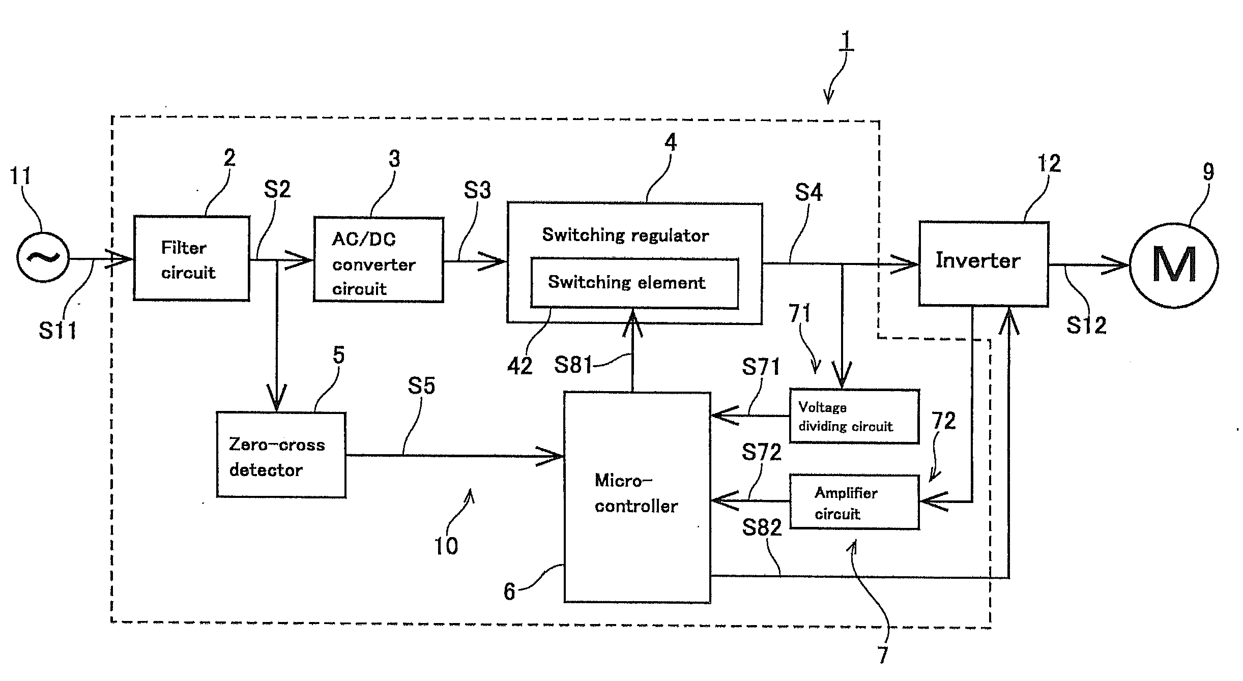
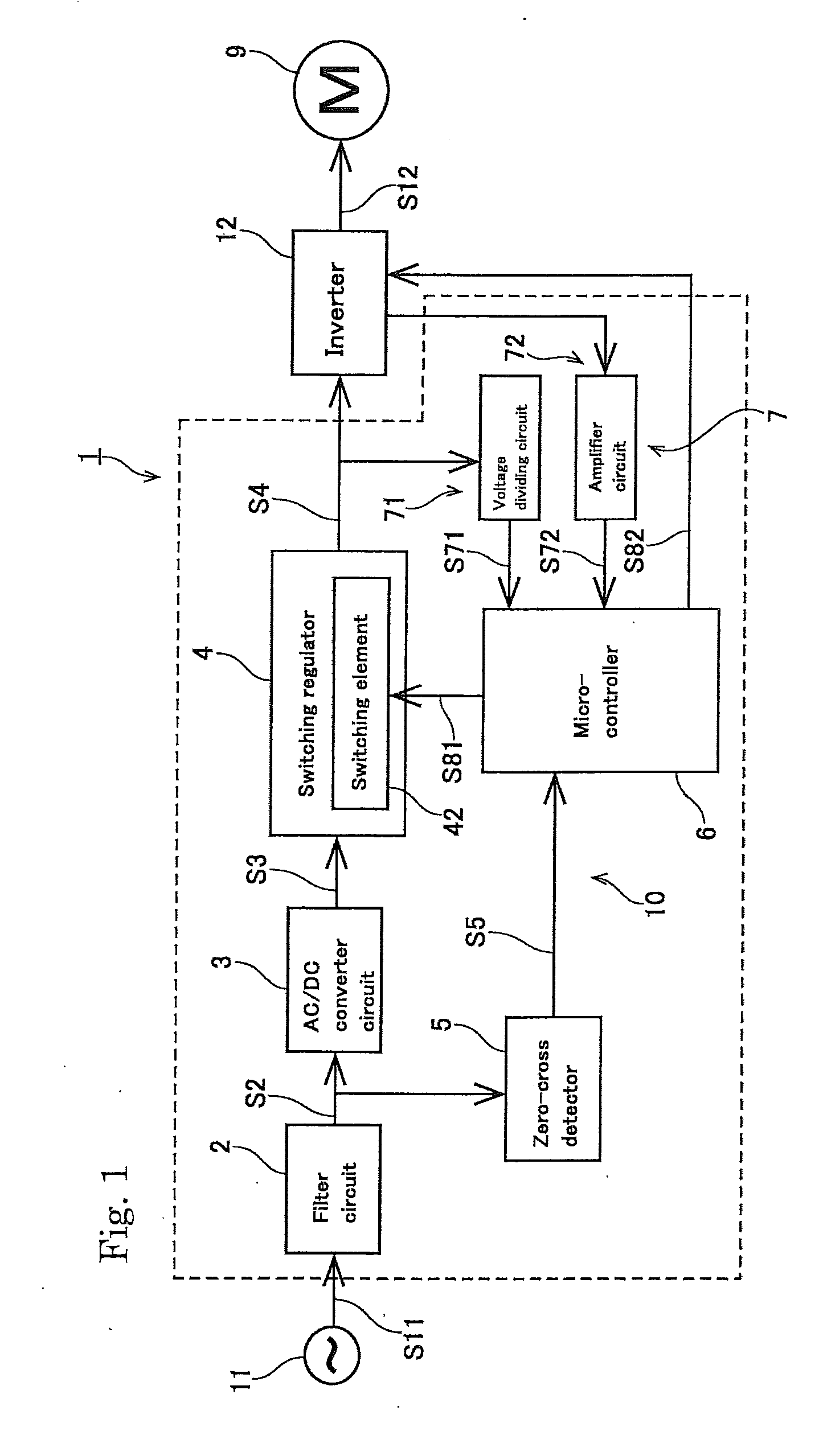
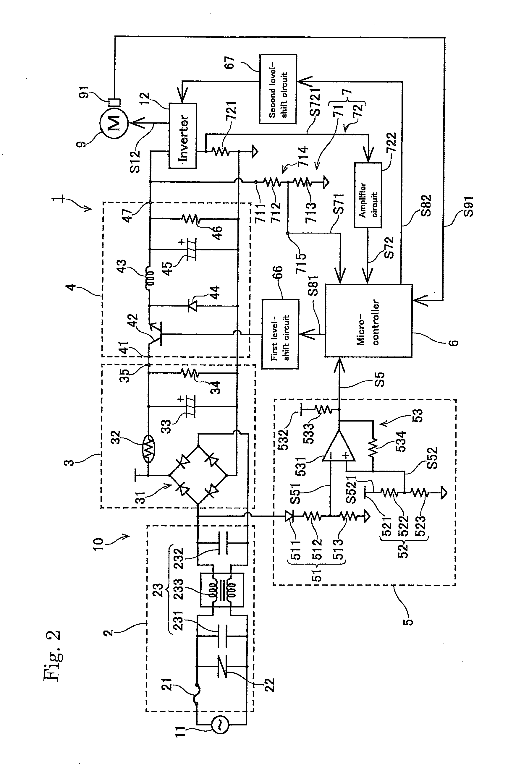
[0020]First, an overall configuration of a motor drive device 1 will be described. FIG. 1 is a block diagram conceptually showing a configuration of the motor drive device 1 in accordance with an embodiment. FIG. 2 is a circuit diagram showing a configuration of the motor drive device 1. FIG. 3 is a block diagram conceptually showing a configuration of a microcontroller 6. FIGS. 4 and 5 are views showing the voltage waveform of each part of the motor drive device 1. FIG. 6 is a view showing an example of a PWM (pulse width modulation) profile of the motor drive device 1.

[0021]The motor drive device 1 supplies a DC voltage to an inverter 12 and controls the driving of a motor 9. As shown in FIG. 1, the motor drive device 1 preferably includes a filter circuit 2, an AC / DC converter circuit 3, a switching regulator 4, a zero-cross detector 5, a microcontroller 6 and a feedback unit 7.

[0022]In the present embodiment, the motor 9 to be driven by the motor drive device 1 is a...

modification example

2. Modification Example

[0065]The exemplary embodiment of the present invention has been described, but the present invention is not limited to the embodiment described above.

[0066]FIG. 7 is a circuit diagram showing a configuration of a motor drive device 1A according to a modification. The motor drive device 1A is a device for controlling the driving of a motor 9A that is a sensorless motor.

[0067]A microcontroller 6A serving as a motor drive control unit 82A outputs a position detection pulse signal S821A, instead of a motor drive signal for driving the motor 9A, to an inverter 12A through a second level shift circuit 67A in order to estimate the position of the rotor of the motor 9A. When the inverter 12A supplies a position detection current S121A to the motor 9A in response to the position detection pulse signal S821A, an electromotive force is generated in the motor 9A, and a current flows through a shunt resistor 721A. Accordingly, a shunt voltage S721A having a voltage value ...


PUM


Abstract

A motor drive device includes a constant voltage power supply and a motor drive control unit. The constant voltage power supply includes an AC/DC converter, a zero-cross detector, a switching control unit and a switching regulator. The AC/DC converter converts an AC voltage supplied from an AC voltage source into a DC voltage. The zero-cross detector detects a zero-cross point of the AC voltage, and outputs a zero-cross detection signal. The switching control unit outputs a switching control signal based on the zero-cross detection signal. The switching regulator has a switching element. The motor drive control unit outputs a motor drive signal for driving a motor to the inverter. The AC/DC converter has a rectifier circuit and a smoothing capacitor. The switching regulator performs switching on a first DC voltage in accordance with the switching control signal at a timing corresponding to the zero-cross point.

Description

CROSS REFERENCE TO RELATED APPLICATIONS[0001]The present invention claims priority under 35 U.S.C. §119 to Japanese Application No. 2013-241670 filed Nov. 22, 2013, the entire content of which is incorporated herein by reference.BACKGROUND OF THE INVENTION[0002]1. Field of the Invention[0003]The present invention relates to a motor drive device.[0004]2. Description of the Related Art[0005]Conventionally, there is known a motor drive device having a constant voltage power supply. In order to drive a brushless DC motor using an AC voltage source, the constant voltage power supply converts an AC voltage supplied from the AC voltage source into a DC voltage. Further, conventionally, there is known a constant voltage power supply having a smoothing capacitor and a rectifier circuit for rectifying an AC voltage.[0006]A conventional constant voltage power supply is disclosed in, e.g., Japanese Patent Application Publication No. 1995-123721. As disclosed in Japanese Patent Application Publi...

Claims


Application Information

Patent Timeline
IPC IPC(8): H02P6/00H02M3/155H02M7/48H02P21/22H02P23/26H02P27/06H02P27/08
CPCH02P6/00H02P7/29H02P27/06H02P31/00H02M1/4291H02M7/04Y02B70/10Y02P80/10
Inventor SHITABO, HIROYUKI
Owner NIDEC TECHNO MOTOR CORP
Why Eureka
Try Eureka