
Differential blade design for propeller noise reduction

Active Publication Date: 2015-05-28
HAMILTON SUNDSTRAND CORP
View PDF10 Cites 25 Cited by
  • Summary
  • Abstract
  • Description
  • Claims
  • Application Information

AI Technical Summary

Benefits of technology

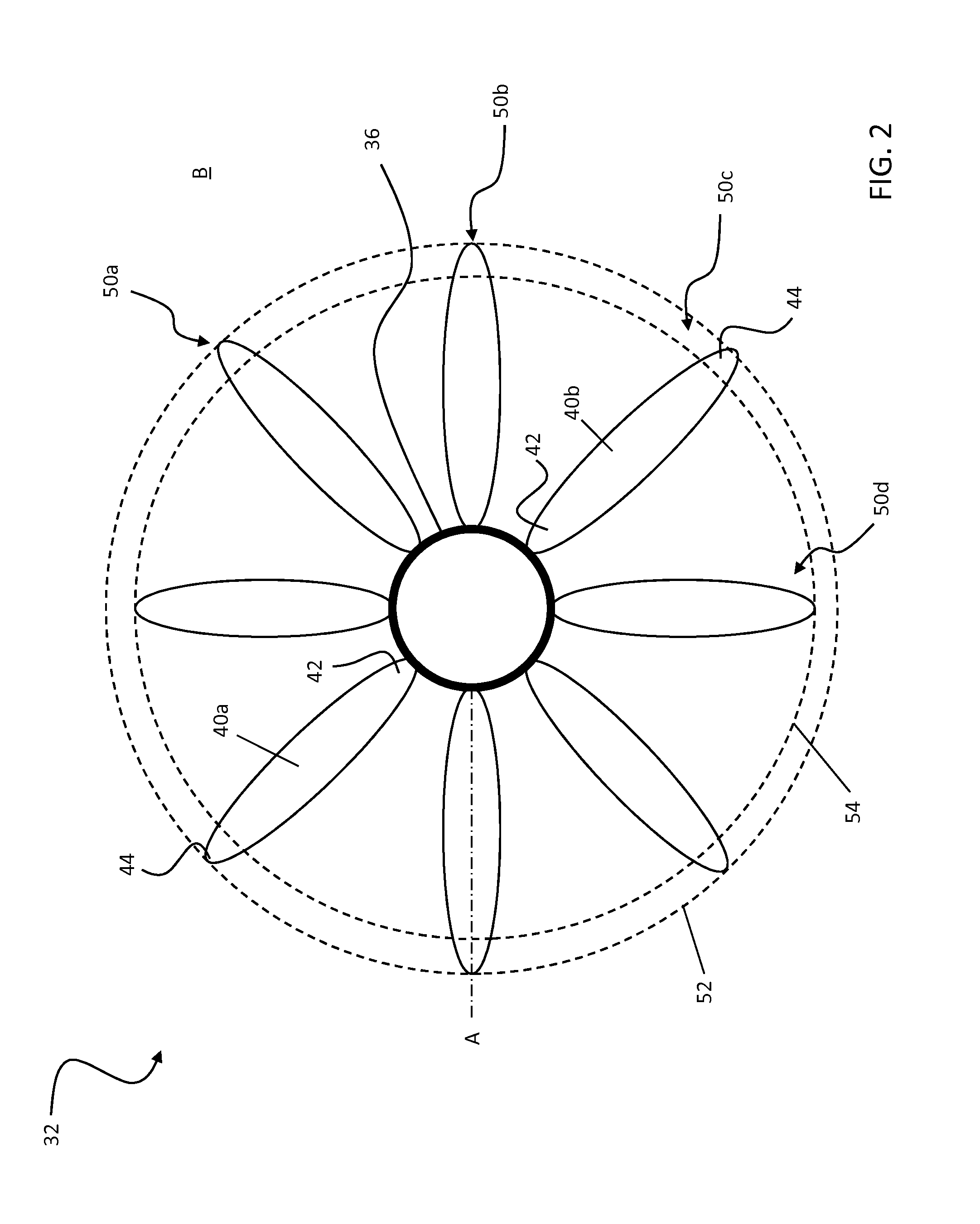
The invention relates to a type of propeller with two groups of blades mounted on a hub. The first group has blades that are different from those of the second group in their geometric characteristics. The propeller blades are identical in design and are evenly spaced around the hub. The first group of blades creates a different noise signature compared to the second group, which helps reduce noise and improve propeller performance.

Problems solved by technology

Propeller driven aircrafts have near field and interior noise that include noise signature content related to operation of the propeller.
Near field noise outside of the aircraft can create pressure fluctuations that may fatigue the structure of the aircraft.
This near field noise can also result in interior noise, audible within the fuselage, making the aircraft less comfortable for passengers situated therein.
Propeller noise will also propagate to the far field becoming an annoyance factor for those living near an airport.

Method used


Image

  • Differential blade design for propeller noise reduction
  • Differential blade design for propeller noise reduction
  • Differential blade design for propeller noise reduction

Examples


Embodiment Construction

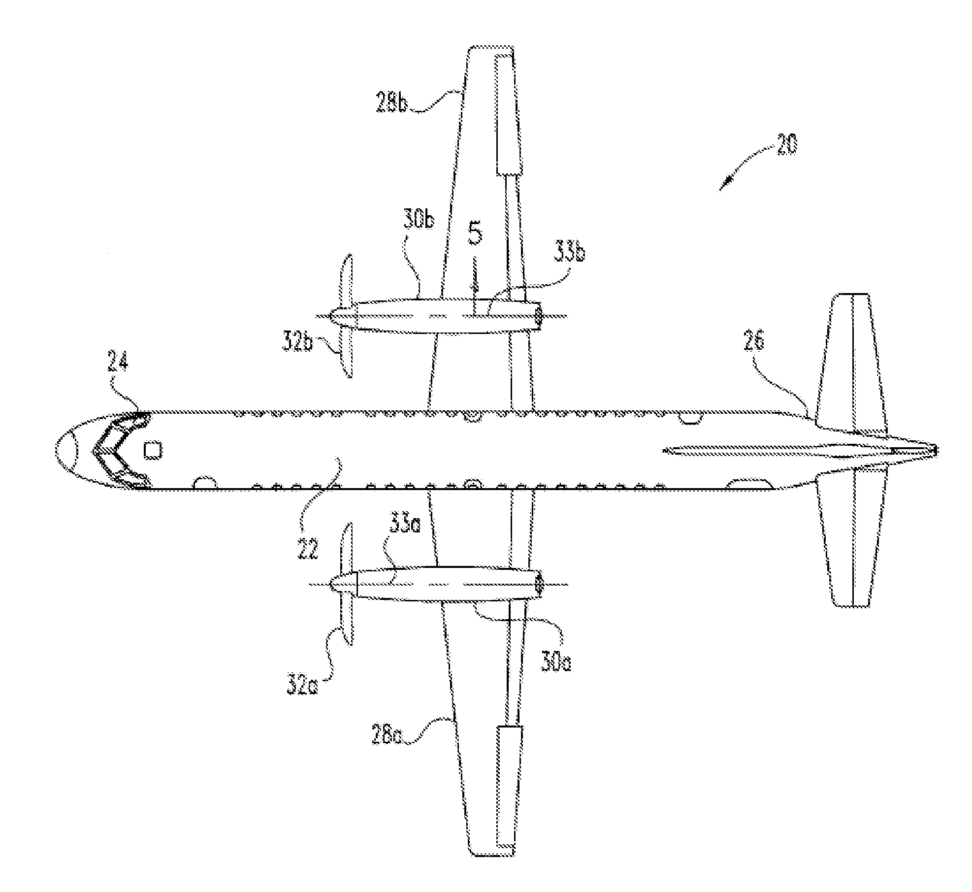
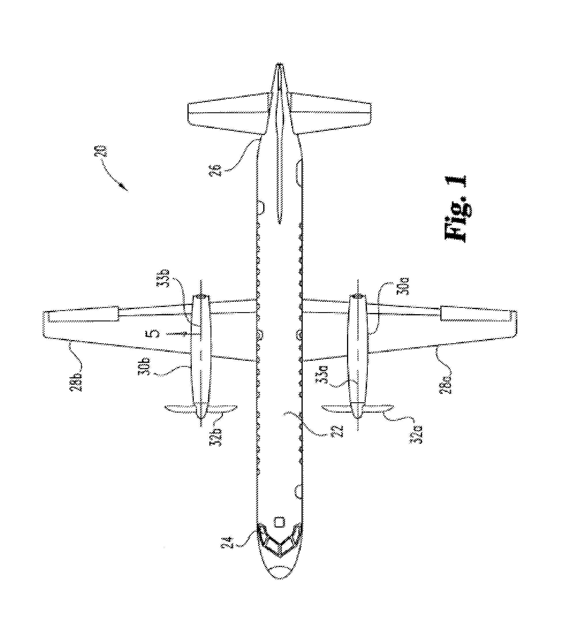
[0015]FIG. 1 is a top plane view of an aircraft 20 including a fuselage 22, a cockpit 24, and a tail 26. Attached to the fuselage 22 are left and right wings 28a, 28b respectively. Each wing 28 incorporates a nacelle 30 which includes a propeller 32 powered by an engine 34. Each propeller 32 is configured to rotate about a rotational axis 33. Though a specific aircraft is illustrated and described herein, other propeller driven aircrafts are within the scope of the invention.

[0016]Referring now to FIGS. 2-4, a propeller 32 of an aircraft 20 is illustrated in more detail. The propeller 32 includes a plurality of propeller blades 40 individually mounted at a first or root end 42 to a centrally located propeller hub 36. The propeller hub 36 is configured to rotate about the rotational axis 33. Each of the plurality of propeller blades 40 extends radially outward from the hub 36 such that the second end 44 of each blade 40 is generally arranged within a plane B. Plane B is oriented subs...


PUM


Abstract

A propeller is provided including a hub and a first blade group and a second blade group. The first blade group includes at least one first propeller blade and the second blade group includes at least one second propeller blade. The at least one first propeller blade and the at least one second propeller blade are mounted to and equidistantly spaced about the hub. The at least one first propeller blade of the first blade group has at least one geometric characteristic different from the at least one propeller blade of the second blade group. The different blade groups will generate different noise signatures over a wider range of frequencies allowing for the design of low noise propeller systems.

Description

BACKGROUND OF THE INVENTION[0001]Embodiments of the invention relate to a propeller of an aircraft, and more particularly, to reducing the noise generated by the propeller during operation of the aircraft.[0002]Propeller driven aircrafts have near field and interior noise that include noise signature content related to operation of the propeller. Near field noise outside of the aircraft can create pressure fluctuations that may fatigue the structure of the aircraft. This near field noise can also result in interior noise, audible within the fuselage, making the aircraft less comfortable for passengers situated therein. Propeller noise will also propagate to the far field becoming an annoyance factor for those living near an airport.[0003]Various methods have been employed to reduce propeller noise, including the use of swept blade propellers, increased blade count, active noise control, and tuned mechanical dampers within or on the fuselage. On multi-engine aircrafts, angular phasin...

Claims


Application Information

Patent Timeline
IPC IPC(8): F01D5/02
CPCF01D5/02B64C11/18
Inventor HENZE, CHAD M.SHANNON, DANIEL W.SCHLINKER, ROBERT HANS
Owner HAMILTON SUNDSTRAND CORP
Learn More