
Cochlear Electrode With Apical Lateral Wall Section and Basal Modiolar Hugging Section

Active Publication Date: 2015-05-28
MED EL ELEKTROMEDIZINISCHE GERAETE GMBH
View PDF4 Cites 14 Cited by
  • Summary
  • Abstract
  • Description
  • Claims
  • Application Information

AI Technical Summary

Benefits of technology

The present invention is about an electrode array for a cochlear implant that can be implanted in a patient's cochlea. The array has a flexible trunk and separate basal branch that can stimulate adjacent neural tissue. The array is designed to follow the natural contour of the cochlea during surgery and is easily removable from the cochlea. The invention also includes a retraction feature and an insertion tube for ease of extraction. The invention also involves magnetic elements that can help guide the placement of the electrode array towards the modiolar wall. Overall, the invention provides an improved and effective electrode array for cochlear implants.

Problems solved by technology

Hearing is impaired when there are problems in the ability to transduce external sounds into meaningful action potentials along the neural substrate of the cochlea.
Some electrode array designs are pre-curved, though a drawback of that approach is that a special electrode insertion tool is needed which keeps the electrode array straight until the point of insertion.
On the other hand, modiolar hugging electrode arrays create greater trauma during insertion (especially via a cochleostomy opening) and also during explantation.
However, after insertion there is no opportunity for the surgeon to correct and optimize the position of the electrode array.

Method used


Image

  • Cochlear Electrode With Apical Lateral Wall Section and Basal Modiolar Hugging Section
  • Cochlear Electrode With Apical Lateral Wall Section and Basal Modiolar Hugging Section
  • Cochlear Electrode With Apical Lateral Wall Section and Basal Modiolar Hugging Section

Examples


Embodiment Construction

[0025]Embodiments of the present invention are directed to implantable electrode arrays for cochlear implants that is very atraumatic, but also very effective in terms of focused stimulation. This is achieved with an electrode array that has two different sections. An apical section of the electrode array remains straight to be atraumatic and protect the delicate anatomical structures. A basal branch of the electrode array is designed to be positioned close to the modiolar window.

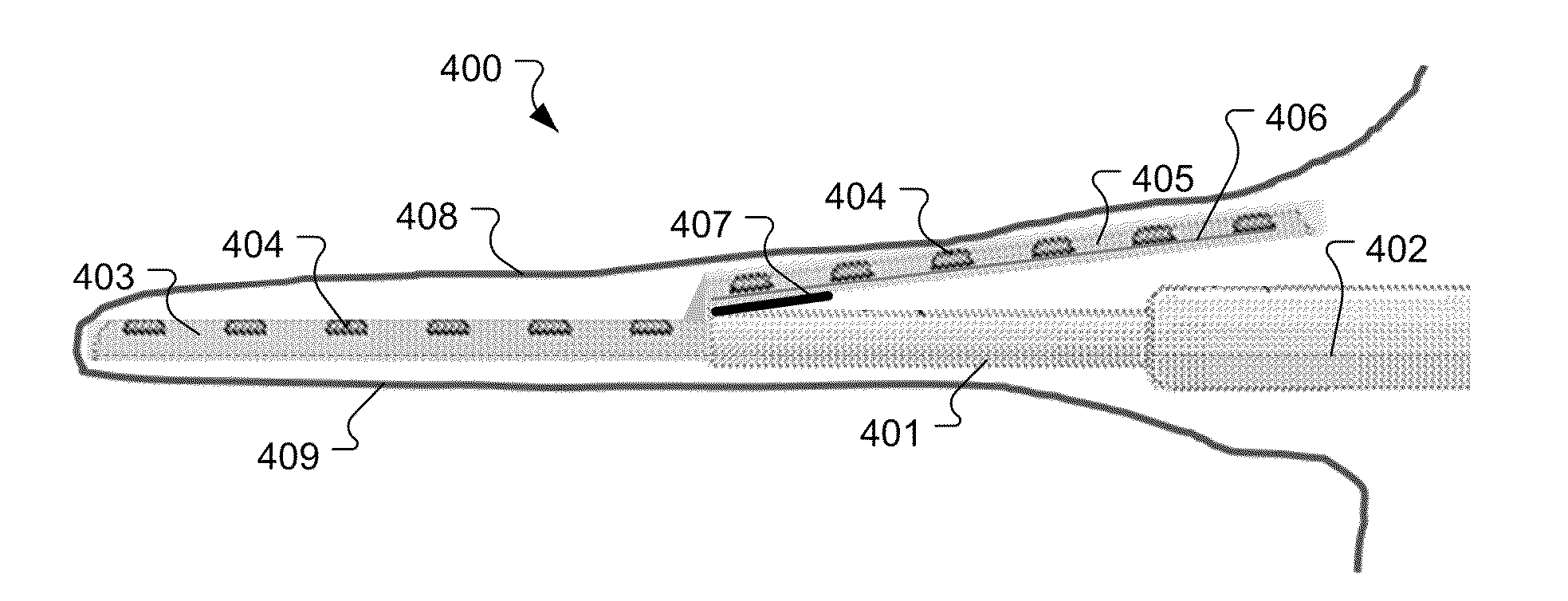
[0026]FIGS. 4A-4C show structural details of an implantable electrode array 400 that includes an array trunk 401 that extends along a center axis 402 into the scala tympani from an insertion opening in an outer surface of a patient cochlea. An apical section 403 extends out from the distal end of the array trunk 401 along the center axis 402. The apical section 403 has multiple stimulation contacts 404 distributed along its outer surface for delivering electrical stimulation signals to adjacent neural tissu...


PUM


Abstract

An implantable electrode array for a cochlear implant has an array trunk that extends along a center axis from an insertion opening in an outer surface of a patient cochlea into the scala tympani. An apical section extends along the center axis from a distal end of the array trunk and a basal branch is separate from the array trunk and extends back from the distal end of the array trunk towards the insertion opening. The apical section follows along an outer lateral wall of the scala tympani during surgical insertion to attain a final insertion position towards the outer lateral wall in an apical portion of the scala tympani beyond a first basal turn of the cochlea. The basal branch attains a final insertion position towards an inner modiolar wall by the first basal turn of the cochlea with the basal branch stimulation contacts facing the inner modiolar wall.

Description

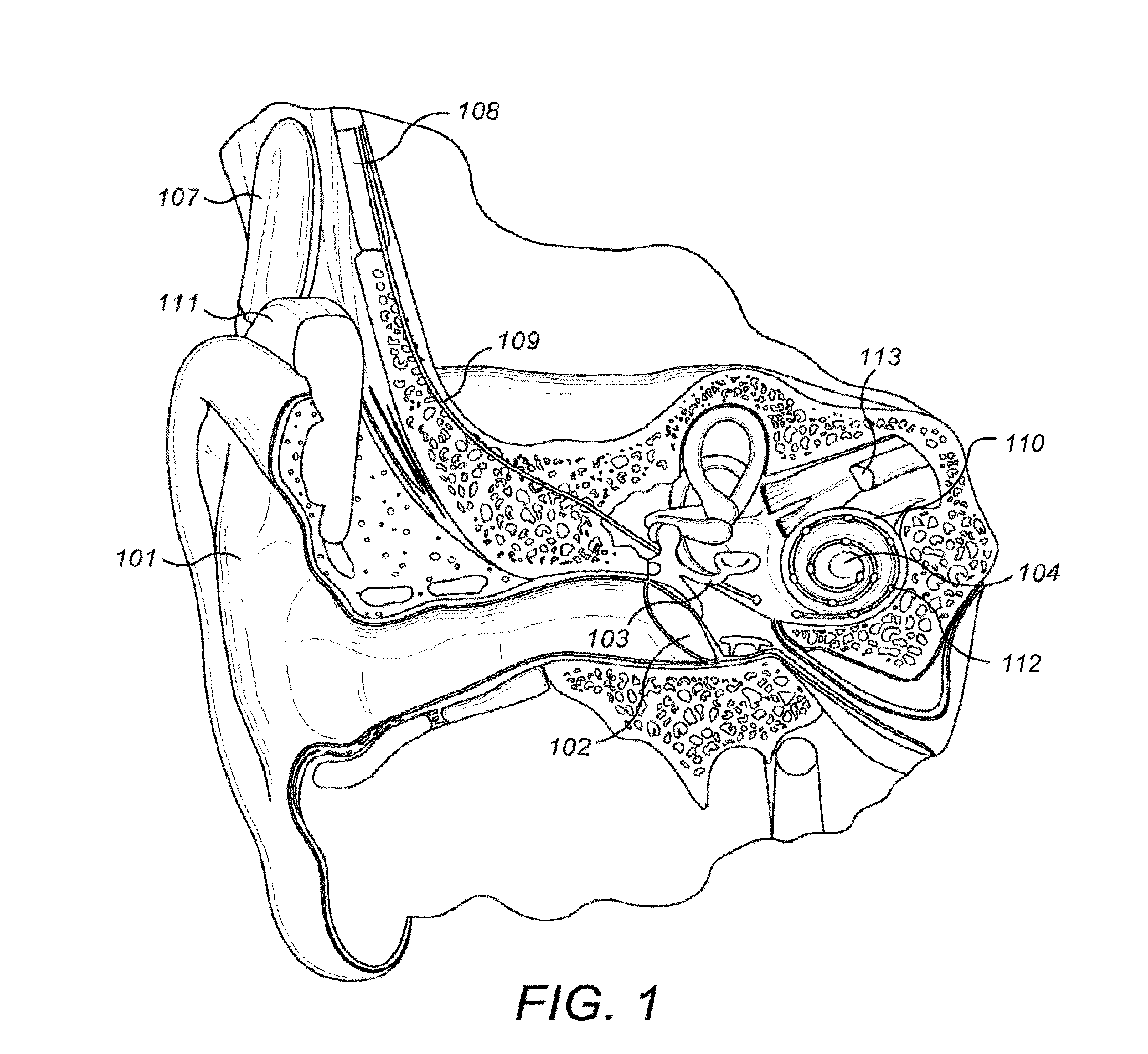
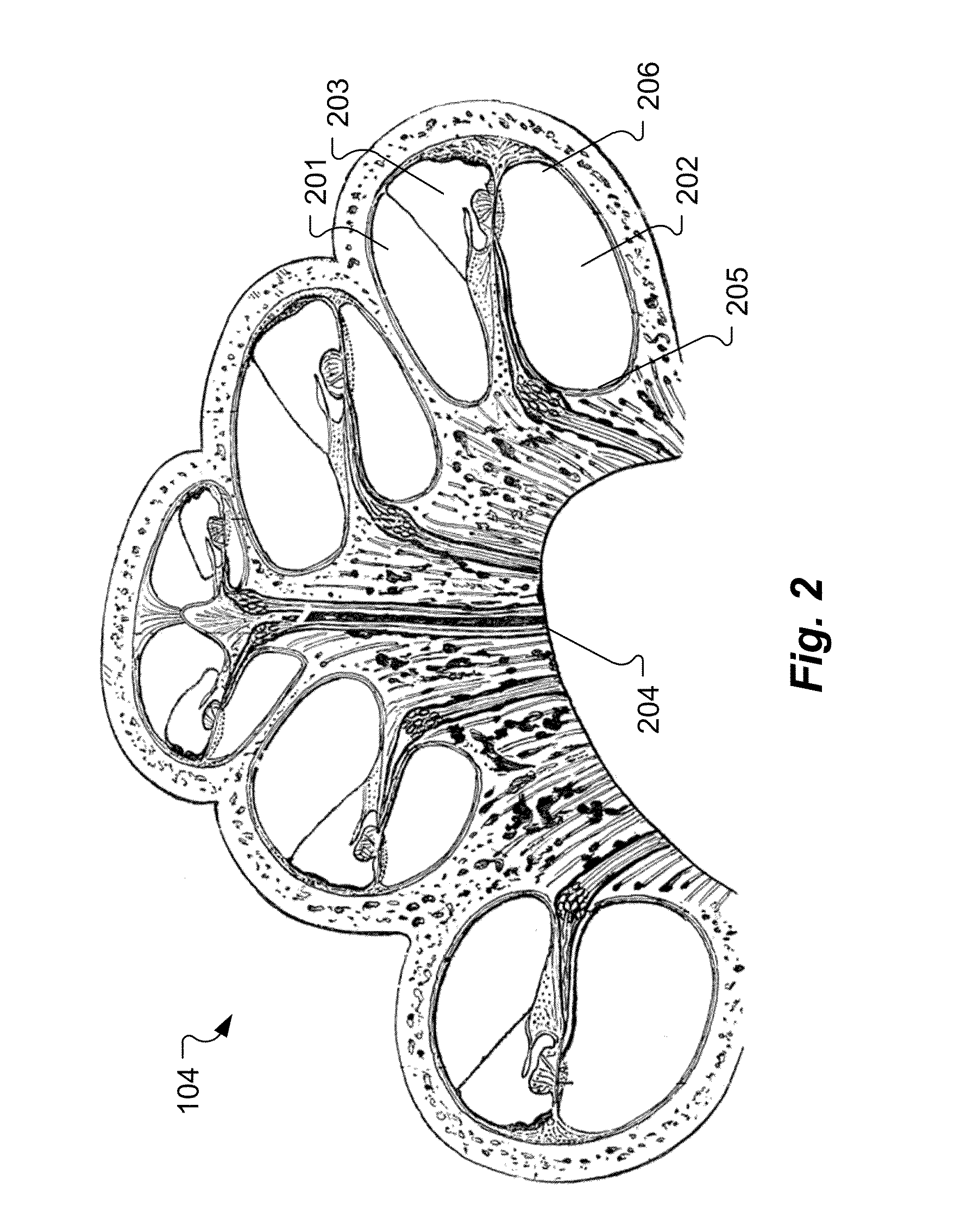
[0001]This application is a continuation in part of U.S. patent application Ser. No. 14 / 514,963, filed Oct. 15, 2014, which claims priority from U.S. Provisional Patent Application 61 / 890,923, filed Oct. 15, 2013, both of which are incorporated herein by reference in their entireties.FIELD OF THE INVENTION[0002]The present invention relates to medical implants, and more specifically to an implantable electrode for use in cochlear implant systems in patients having a malformed cochlea.BACKGROUND ART[0003]A normal ear transmits sounds as shown in FIG. 1 through the outer ear 101 to the tympanic membrane (eardrum) 102, which moves the bones of the middle ear 103 (malleus, incus, and stapes), which in turn vibrate the oval window and round window openings of the cochlea 104.[0004]The cochlea 104 is a long narrow duct wound spirally about its axis for approximately two and a half turns. FIG. 2 shows a cross-sectional view of the cochlea 104 in which the spiral shape is evident. The first...

Claims


Application Information

Patent Timeline
IPC IPC(8): A61N1/05A61M31/00
CPCA61M31/002A61N1/0541
Inventor JOLLY, CLAUDEDHANASINGH, ANANDHAN
Owner MED EL ELEKTROMEDIZINISCHE GERAETE GMBH
Learn More