
Method for controlling a wind park

a technology for wind farms and wind farms, applied in the direction of process and machine control, computer control, instruments, etc., can solve the problems of loss of stability in the grid, all the more serious, and achieve the effect of preventing internal controls

Active Publication Date: 2015-05-28
WOBBEN PROPERTIES GMBH
View PDF6 Cites 41 Cited by
  • Summary
  • Abstract
  • Description
  • Claims
  • Application Information

AI Technical Summary

Benefits of technology

The patent relates to a method for safely feeding electrical power into an electrical grid. It involves quickly and frequently identifying the voltage of the grid and comparing it with a set point value. This allows for real-time decision-making to ensure the grid operates in a stable manner. The method takes into account changes in the grid and boundary conditions to detect any divergent behavior that may require special care or adjustment of control specifications. By reducing the amount of power fed into the grid, the method can increase the distance between the operating point and the stability boundary. In summary, the technical effects of the patent are a more efficient and reliable method for safely feeding electrical power into an electrical grid.

Problems solved by technology

There, reference was basically made to the problem that the loss of stability in the grid can basically also occur for wind power installations that are connected to the supply grid for feed-in.
These problems are basically rare, but they are therefore all the more serious.

Method used


Image

  • Method for controlling a wind park
  • Method for controlling a wind park
  • Method for controlling a wind park

Examples


Embodiment Construction

[0080]Below, identical reference signs for similar, but non-identical elements may be provided, or they can also be provided for elements that are only illustrated schematically or symbolically, and that may have different details, but which are not relevant for the respective explanation.

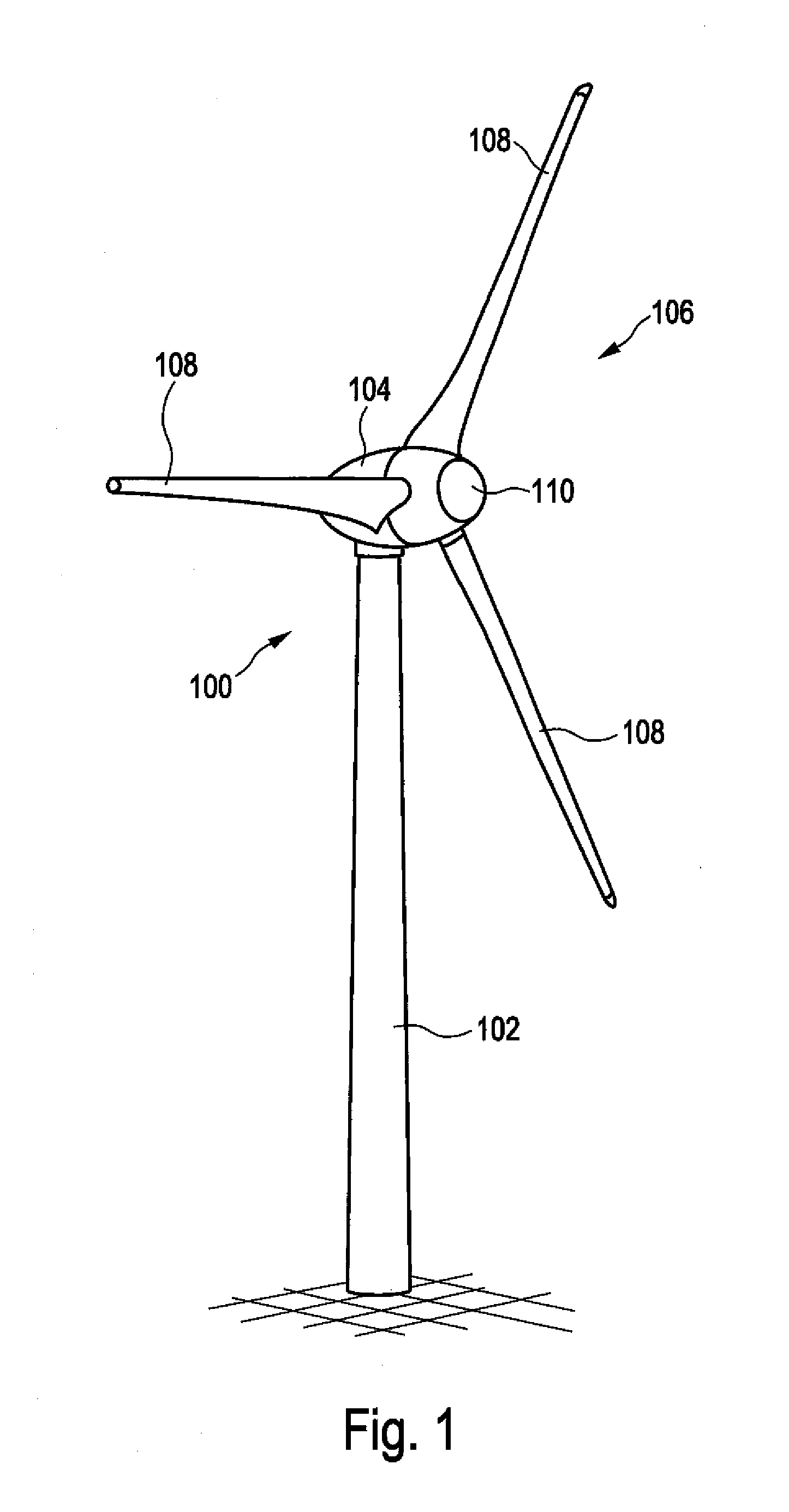
[0081]FIG. 1 Shows wind power installation 100 with tower 102 and nacelle 104. Rotor 106 with three rotor blades 108 and spinner 110 is located on nacelle 104. Rotor 106 is set in operation by the wind in a rotating movement, thereby driving a generator in nacelle 104.

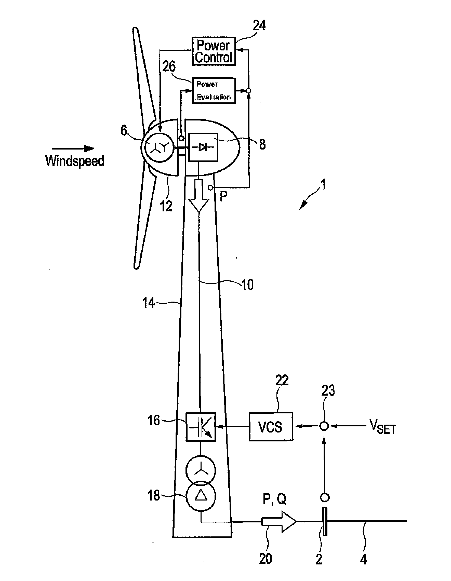
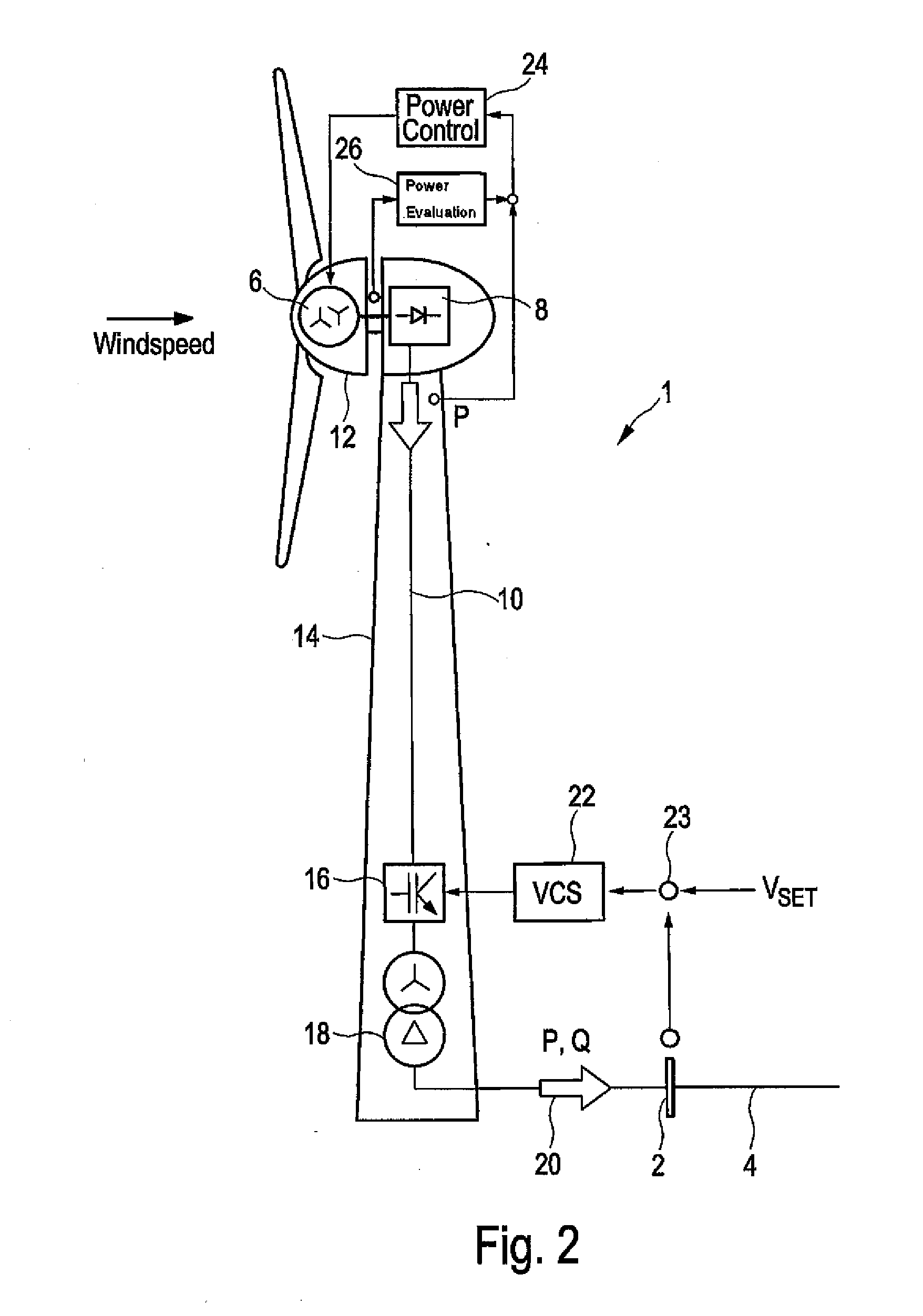
[0082]FIG. 2 shows a schematic view of a wind power installation 1 connected to electrical supply grid 4 over grid connection point 2. Electrical supply grid 4 is simply referred to as grid 4 or network 4, whereby these terms are used synonymously.

[0083]Wind power installation 1 comprises generator 6, which is driven by the wind, thereby producing electrical energy. One of the embodiments of generator 6 is an electrically excited mult...


PUM


Abstract

The invention relates to a method for controlling a wind park comprising several wind power installations to feed electrical power into an electrical AC grid at a point of common coupling (PCC). The method comprises feeding a 3-phase current at a point of common coupling, identifying a grid voltage on the point of common coupling, comparing the grid voltage that was identified on point of common coupling with at least one predetermined set point value, determining set point values for wind power installations depending on a comparison conducted to meet a stability criterion on point of common coupling, passing the determined set point values to plant control units of the individual wind power installations, and producing electrical current at each of the wind power installations depending on the predetermined set point values to be jointly fed in on point of common coupling.

Description

BACKGROUND[0001]1. Technical Field[0002]The present invention relates to a method for controlling a wind park, as well as such a respective wind park. In particular, the present invention relates to controlling a wind park to feed electrical power into an electrical AC grid on a point of common coupling, as well as such a wind park.[0003]2. Description of the Related Art[0004]Wind parks are generally known, they relate to several wind power installations that belong together in organizational terms. In particular, all wind power installations that belong to a wind park feed into an electrical AC grid on a point of common coupling. Usually, each wind power installation itself generates an electrical current that is to be fed, i.e., usually a 3-phase electrical current that is to be fed in. For this purpose, the wind power installation refers to the voltage in the electrical AC grid that is to be fed in, which is also simply referred to below as grid, in particular according to the am...

Claims


Application Information

Patent Timeline
Patent Type & Authority Applications(United States)
IPC IPC(8): F03D7/04G05B15/02
CPCG05B15/02F03D7/048F03D7/0284H02J3/16H02J3/26Y02E40/50Y02E10/72Y02E10/76Y02E40/30H02J2300/28H02J3/48H02J3/381H02J3/50
Inventor DIEDRICHS, VOLKER
Owner WOBBEN PROPERTIES GMBH
Learn More