
Method of detecting stack overflows and processor for implementing such a method

Active Publication Date: 2015-05-28
THALES SA
View PDF8 Cites 19 Cited by
  • Summary
  • Abstract
  • Description
  • Claims
  • Application Information

AI Technical Summary

Benefits of technology

The invention aims to provide a method of detecting stack overflows in a simple and efficient way. This method uses both hardware and software means and can detect overflows as soon as they occur, minimizing their impact. The system also allows the developer to size the stacks and recover from context switching between threads or processes. The result is a more effective and efficient method for detecting and managing stack overflows.

Problems solved by technology

A problem frequently encountered with stacks is the overflowing or the space allocated to one of them, mainly because of programming errors (unlimited recursive loops, unexpected branches, etc.) or functional defects (incorrect analysis of the stack size, insufficient memory allocation, etc.).
Such a problem is difficult to detect and to analyze when it shows up after a delay, when the process the stack of which has been corrupted is activated.
This solution was costly in terms of execution time and did not provide complete protection against the risks of overflow.
Moreover, it provided no assistance to the programmer in sizing the stacks so as to avoid overflow errors.
If the stack pointer overflows, the application attempts to read or write in this prohibited area and produces a page error (program exception).
This technique has a number of disadvantages:it necessitates an MMU, which is a costly hardware unit, is not present in all processors, and is notably absent in many “onboard” processors;programming the MMU is costly and constraining (for this reason, this unit is usually deactivated for most application software);the protection obtained is not absolute: for example, if the local stack of a function reserves a large quantity of memory that is not used, it is possible to pass over the guard space and to carry on in a space to which access is authorized although it is not allocated to the stack.
This technique is costly to implement and can be applied only in the development phase.

Method used


Image

  • Method of detecting stack overflows and processor for implementing such a method
  • Method of detecting stack overflows and processor for implementing such a method
  • Method of detecting stack overflows and processor for implementing such a method

Examples


Embodiment Construction

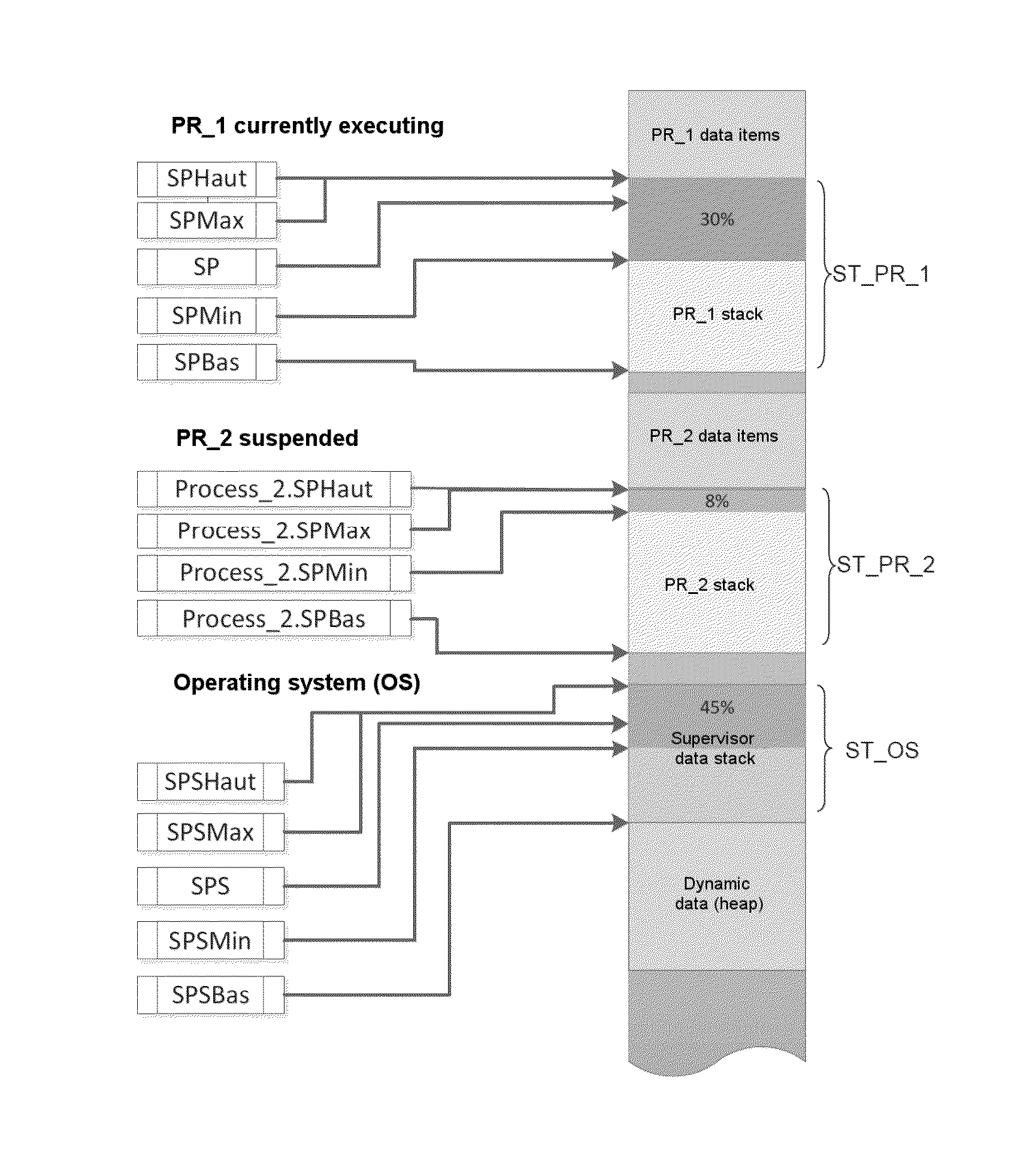
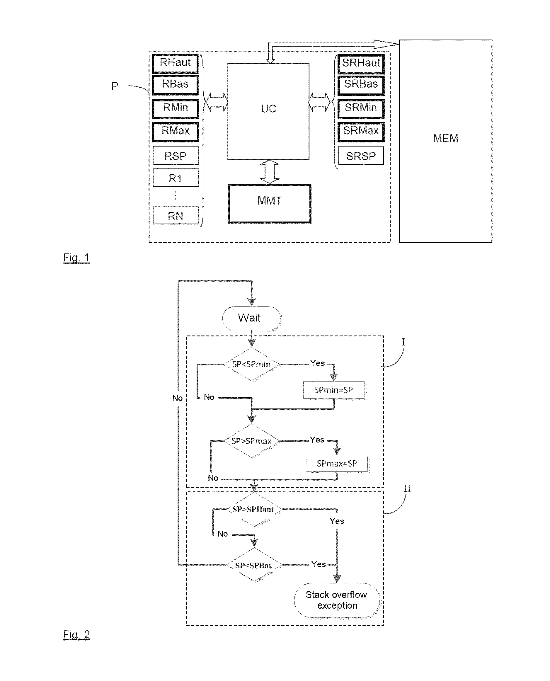
[0037]The processor P in FIG. 1 includes—in a conventional manner—a central processor unit UC exchanging data with a memory MEM (which in this instance is not part of the processor itself), a set of N “generic” registers R1-RN and two registers RSP and SRSP for storing a stack pointer for the processes executed in user mode and in supervisor mode, respectively. The processor also includes two sets of dedicated registers used to detect stack overflows: a first set comprising the registers RHaut, RBas, RMin and RMax, for the user mode, and a second set comprising the registers SRHaut, SRBas, SRMin and SRMax, for the supervisor mode; as well as a hardware processor module MMT, shown as a separate component but which may in fact be integrated into the central processor unit. In the FIG. 1 embodiment, all exchanges of data are effected via the central processor unit UC; alternatively, data could be exchanged directly between the dedicated registers and the hardware processor module MMT a...


PUM


Abstract

A method of detecting stack overflows includes the following steps: storing in at least one dedicated register at least one data item chosen from: a data item (SPHaut) indicating a maximum permitted value for a stack pointer, and a data item (SPBas) indicating a minimum permitted value for said stack pointer; effecting a comparison between a current value (SP) or past value (SPMin, SPMax) of said stack pointer and said data item or each of said data items; and generating a stack overflow exception if said comparison indicates that said current or past value of said stack pointer is greater than said maximum permitted value or less than said minimum permitted value. A processor for implementing such a method is also provided.

Description

CROSS-REFERENCE TO RELATED APPLICATION[0001]This application claims priority to foreign French patent application No. FR 1302695, filed on Nov. 22, 2013, the disclosure of which is incorporated by reference in its entirety.FIELD OF THE INVENTION[0002]The invention relates to a method of detecting stack overflows and to a processor for implementing such a method.BACKGROUND[0003]Programs written in high-level languages (C, C++, ADA, etc.) require data stacks to isolate the local variables of each function. Generally, for a given thread or process, there is only one stack (“call stack”) and it grows on each interleaving of functions, and then shrinks when a function terminates (return). The memory of a computer generally stores a plurality of stacks, one for each thread or process.[0004]A problem frequently encountered with stacks is the overflowing or the space allocated to one of them, mainly because of programming errors (unlimited recursive loops, unexpected branches, etc.) or func...

Claims


Application Information

Patent Timeline
IPC IPC(8): G06F9/30G06F9/46G06F9/48
CPCG06F9/30134G06F9/462G06F9/4843G06F9/3861G06F9/5016G06F21/52
Inventor GROSSI, PHILIPPEDAVID, DOMINIQUEBRUN, FRANCOIS
Owner THALES SA
Learn More