Beam monitor system and particle beam irradiation system

a monitor system and beam irradiation technology, applied in the field of beam monitor system and particle beam irradiation system, can solve the problems of increasing costs, complicated monitor system, and large scale, and achieve the effect of improving measurement precision and simple configuration

Active Publication Date: 2015-06-04
HITACHI LTD
View PDF5 Cites 2 Cited by
  • Summary
  • Abstract
  • Description
  • Claims
  • Application Information

AI Technical Summary

Benefits of technology

[0008]An object of the present invention is to provide a beam monitor system having a simple configuration for improving the measurement precision specifying the position and the width in the spot irradiation of the scanning system, and a particle beam irradiation system including the beam monitor system.

Problems solved by technology

For that reason, there arises such a problem that the related art spot position monitor increases the costs because the signal amplifier and the signal processing device are required in association with the number of channels, and a monitor system must be larger-scaled and more complicated in configuration as the number of channels increases more in order to conduct signal amplification and signal processing on all of the channels for detection of the position and the width of the beam.

Method used


Image

  • Beam monitor system and particle beam irradiation system
  • Beam monitor system and particle beam irradiation system
  • Beam monitor system and particle beam irradiation system

Examples


first embodiment

[0020]A description will be given of a beam monitor system and a particle beam irradiation system according to a first embodiment of the present invention with reference to FIGS. 1 to 6.

[0021]In the present invention, the particle beam irradiation system means a system that irradiates an affected area of a patient fixed on a couch (bed device) 10 within a treatment room with an ionized particle beam 12 (for example, proton, heavy ion beam, or the like).

[0022]First, a configuration of the particle beam irradiation system according to the present invention will be described with reference to FIGS. 1 to 3.

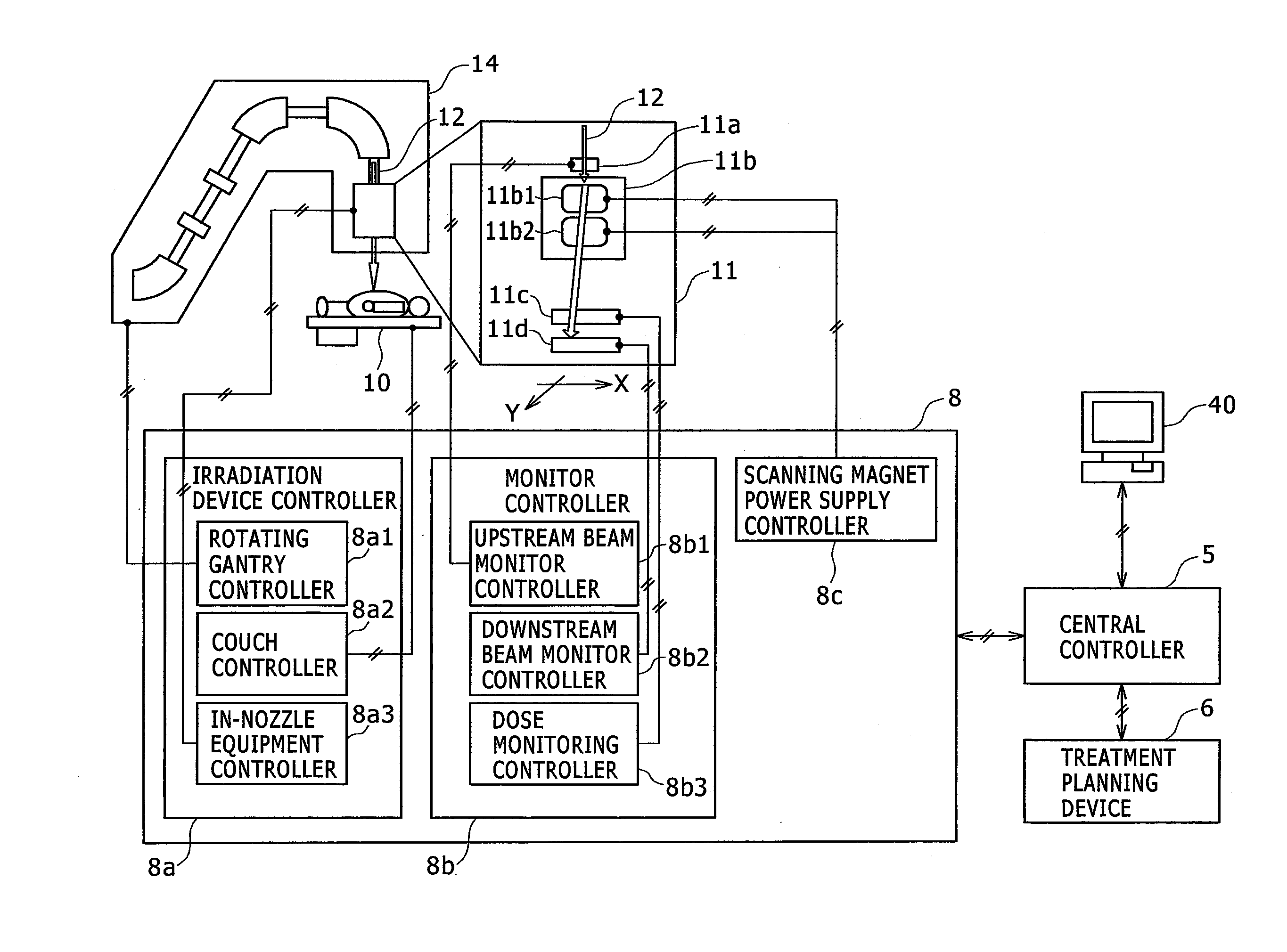
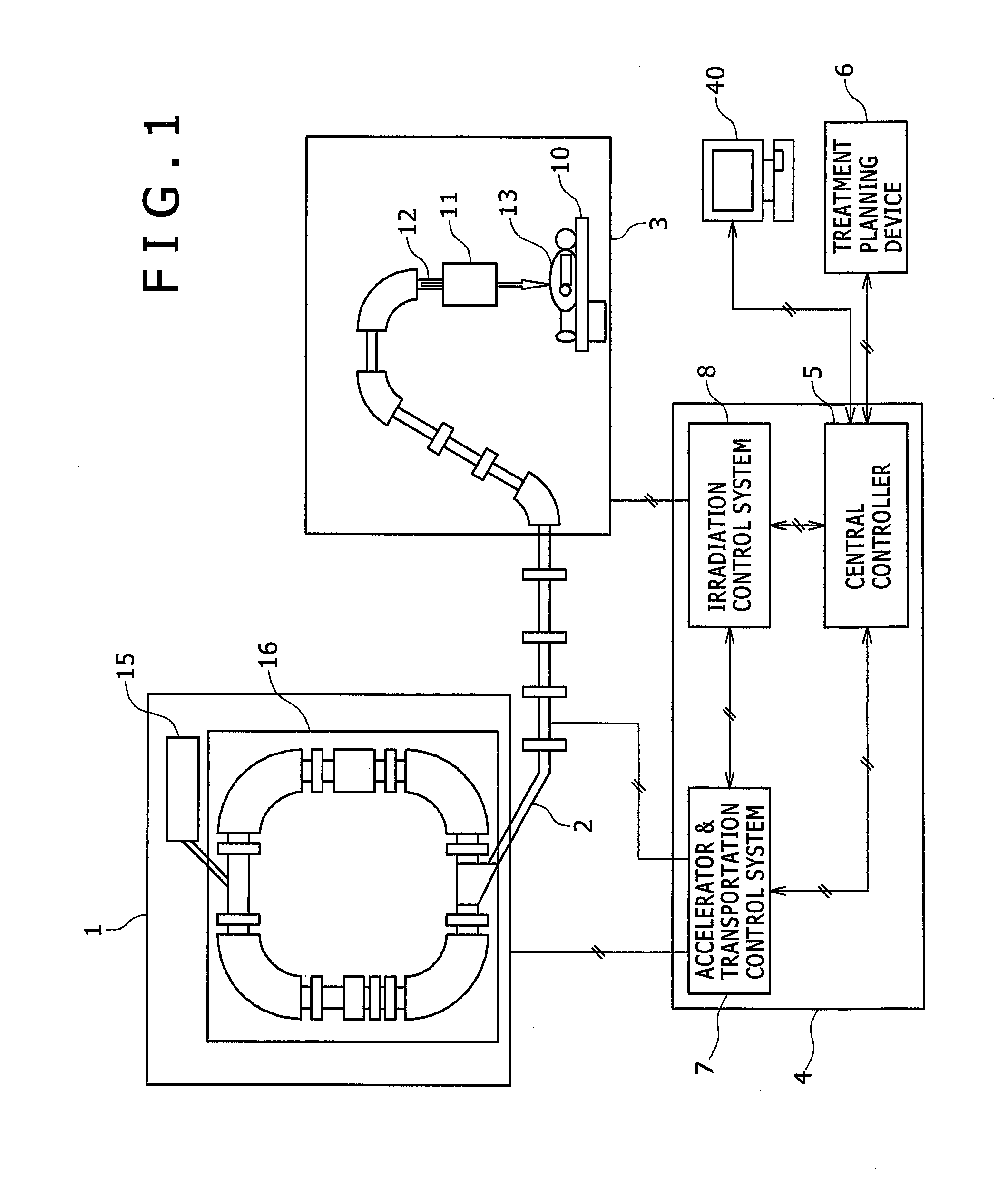
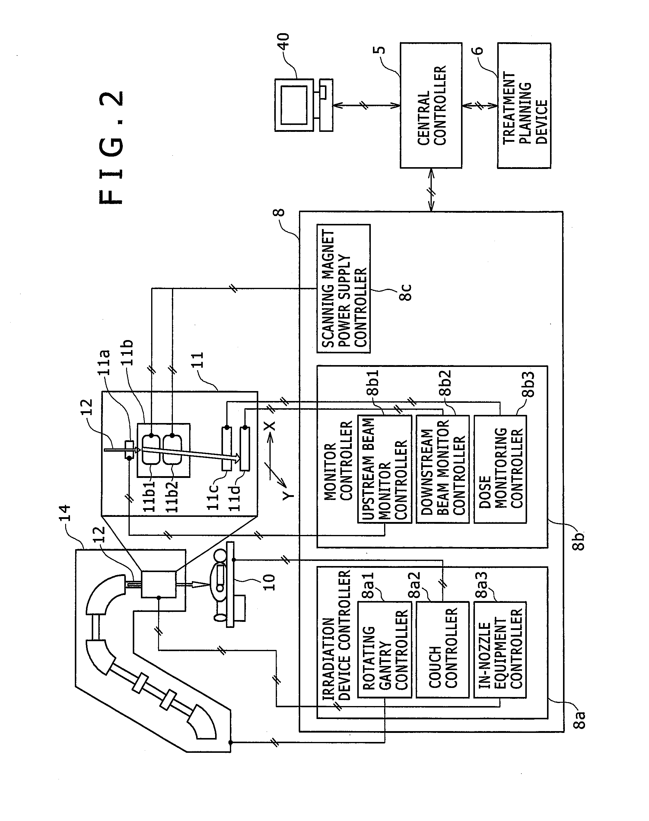
[0023]FIG. 1 is a configuration diagram of this embodiment, FIG. 2 is a configuration diagram of a scanning irradiation device configuring an ionized particle beam irradiation system according to this embodiment, and FIG. 3 is a flowchart of a control of the ionized particle beam irradiation by the scanning irradiation system.

[0024]Referring to FIG. 1, the particle beam irradiation sy...

second embodiment

[0114]A description will be given of a beam monitor system and a particle beam irradiation system according to a second embodiment of the present invention with reference to FIG. 7.

[0115]FIG. 7 is a flowchart of a control of ionized particle beam irradiation by a raster scan system.

[0116]The first embodiment pertains to the particle beam irradiation system having the beam monitor system that monitors the beam position and the beam width in the spot scanning irradiation whereas the particle beam irradiation system according to this embodiment includes a beam monitor system that monitors the beam position and the beam width in the raster scanning irradiation.

[0117]The particle beam irradiation system according to this embodiment includes the beam monitor system that monitors the beam position and the beam width in the raster scanning irradiation, which divides an affected area of the patient 13 into plural layers along a beam traveling direction, and scans the ionized particle beam wh...


PUM


Abstract

A beam monitor system having a simple configuration for improving a measurement precision specifying a position and the width. A beam monitor system, comprising collection electrodes that include a plurality of groups each having a plurality of adjacent wire electrodes, and detect an ionized particle beam passing therethrough, a first signal processing device that sets one wire electrode in the groups of the collection electrodes as a typical wire electrode, receives a detection signal output from the typical wire electrode to process the signal and a beam monitor controller that obtains a beam position of the ionized particle beam that has passed through the wire electrodes on the basis of a processed signal from the first signal processing device.

Description

BACKGROUND[0001]The present invention relates to a monitor system of a beam position in an irradiation system of a charged particle beam (particle beam, ion beam), and more particularly to a beam monitor system in a particle beam irradiation system suitably applied to a particle beam therapy device that irradiates an affected area with a particle beam such as protons or carbon ions for treatment.[0002]A treatment method has been known which irradiates an affected area of a patient suffering from cancer with an ionized particle beam such as protons or carbon ions. An ionized particle beam irradiation system (particle beam extraction device or ionized particle beam extraction device) used for the treatment includes an ionized particle accelerator. An ion beam accelerated by the ionized particle accelerator reaches an irradiation device installed in a rotating gantry through a first beam transportation system and a second beam transportation system disposed in the rotating gantry. The ...

Claims


Application Information

Patent Timeline
Patent Type & Authority Applications(United States)
IPC IPC(8): A61N5/10
CPCA61N5/1065A61N2005/1074A61N5/1077G01T1/2935
Inventor HORI, YOSHIHITOMATSUSHITA, TAKAYOSHIMORIYAMA, KUNIOTADOKORO, MASAHIRO
Owner HITACHI LTD
Why Eureka
Try Eureka