Method, System and Apparatus of Erosion Resistant Filtering Screen Structures

a filtering screen and erosion resistance technology, applied in the field of structures, can solve the problems of screen erosion, particle production from the well, high undesirable, etc., and achieve the effect of reducing the impact area of particles

Inactive Publication Date: 2015-06-04
CHEVROU USA INC
View PDF3 Cites 3 Cited by
  • Summary
  • Abstract
  • Description
  • Claims
  • Application Information

AI Technical Summary

Benefits of technology

The invention is a filtering apparatus that can be used to filter particles from hydrocarbon fluids produced from a wellbore. The apparatus includes a plurality of screens stacked together, with each screen comprising a plurality of first wires and a plurality of second wires woven together. The first wires are oriented parallel to each other in one direction (X direction) and the second wires are oriented parallel to each other in another direction (Y direction) to form an X-Y two-dimensional plane. The first wires present a reduced particle impact area to the particle-laden fluid, which helps to filter out particles from the fluid. The screens can be positioned in the production tubing or inserted into a slot within the tubing. The technical effect of the invention is to provide an effective and efficient way to filter particles from hydrocarbon fluids produced from a wellbore.

Problems solved by technology

One problem in the deployment of such screens is the erosion of the screens by collision of particles upon the screen.
High flow rates, coupled with large amounts of particulate in the flow stream, causes erosion.
When screens become eroded, then particles are produced from the well, which is highly undesirable.
Removing large amounts of sand particles from produced hydrocarbon fluids is expensive, time consuming, and costly.
In many applications for deep wellbores, the financial cost of installing sand exclusion equipment is very high.
The time and effort required to install screens into wellbores is a limiting factor in the economic viability of a producing well.
In some instances, it is impossible, physically or economically, to re-enter a deep wellbore to remove and replace eroded screens.

Method used


Image

  • Method, System and Apparatus of Erosion Resistant Filtering Screen Structures
  • Method, System and Apparatus of Erosion Resistant Filtering Screen Structures
  • Method, System and Apparatus of Erosion Resistant Filtering Screen Structures

Examples


Embodiment Construction

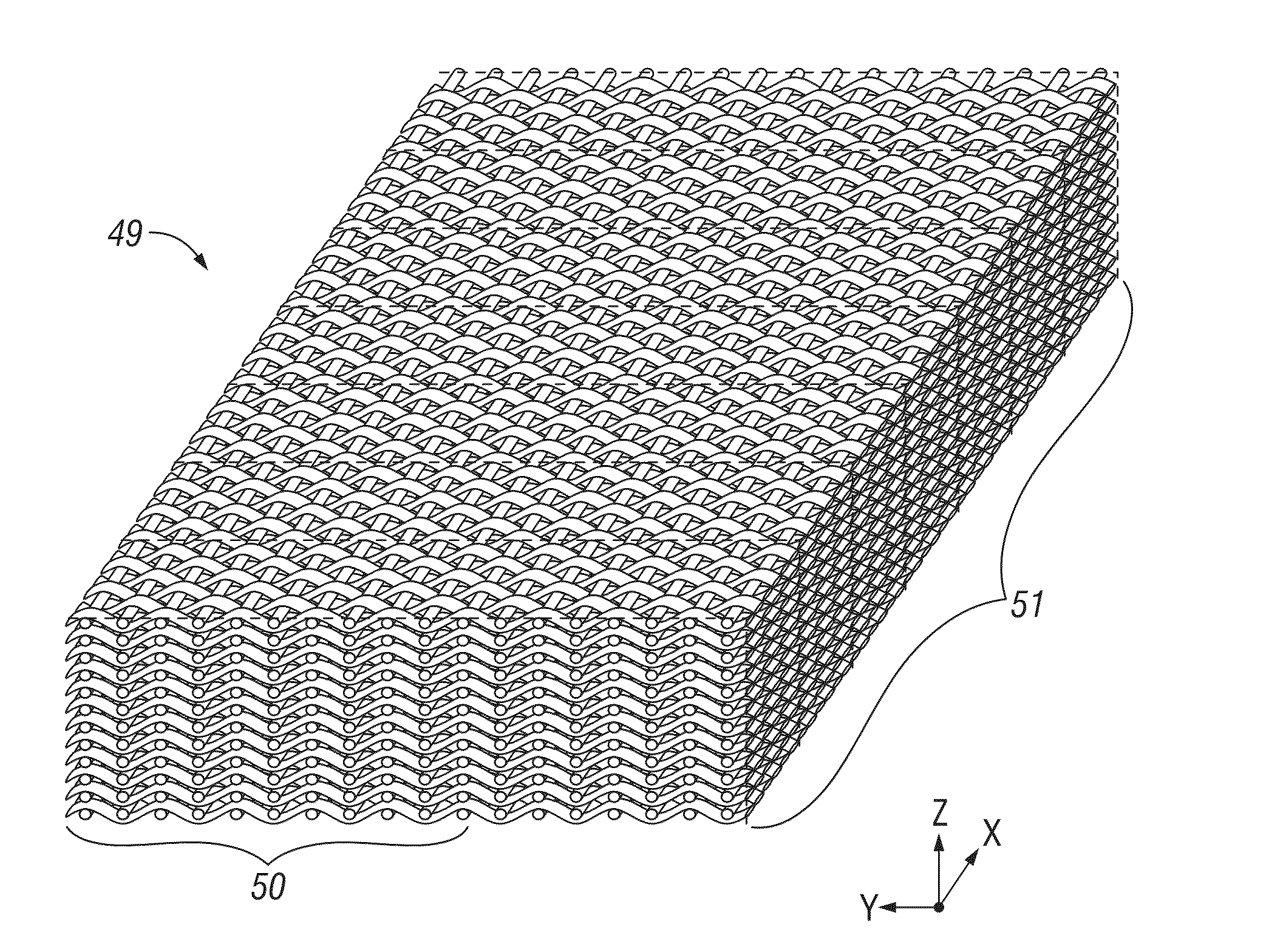
[0042]The invention provides a sand control screen that is more resistant to erosion than conventional sand control screens. By limiting erosion loss, it is not required to hold back the rate of oil and gas production, which is common in instances of sand screen erosion. This facilitates an increase in the oil and gas production rate.

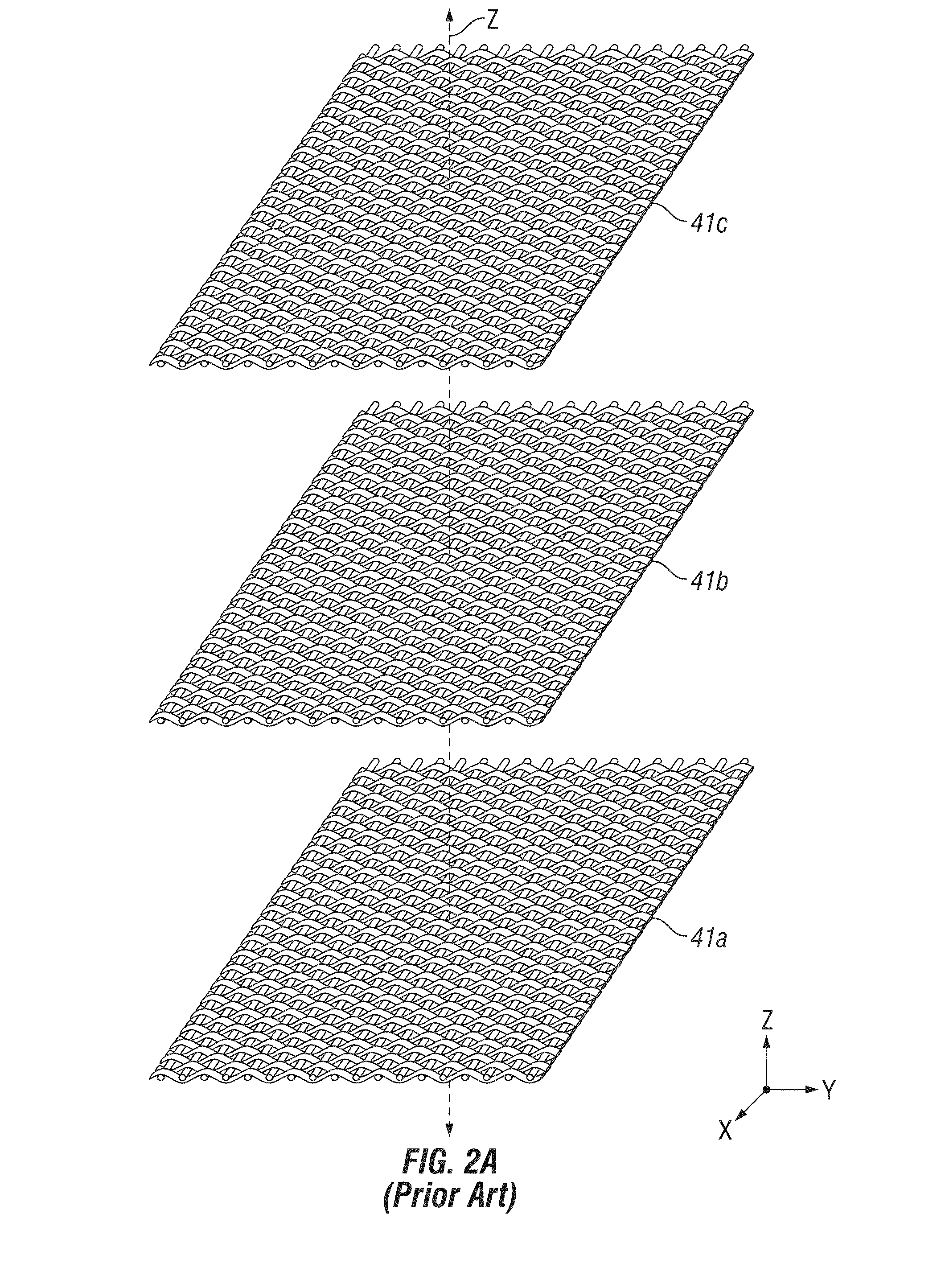
[0043]In the present invention, the screen is applied in multiple stacked configuration to a thickness that is desirable for a given application. An example of a thickness that may be useful is between about ⅜ inches and about ½ inches in total thickness, but it is recognized that larger or smaller total thickness may be employed as well. The required number of screens may be about 2 to about 50 to build the necessary thickness, depending upon the particular application.

[0044]The screen design of the invention employs a plurality of stacked screens as the filtering space by flowing particulate-laden hydrocarbon fluids between the screen layers, and by u...


PUM

PropertyMeasurementUnit
dimensionaaaaaaaaaa
erosionaaaaaaaaaa
flow ratesaaaaaaaaaa

Abstract

An improved particle or sand filtering apparatus, method and system is disclosed. The apparatus may be adapted to filter particles or sand from a particle-laden hydrocarbon fluid by employing a stacked multi-layered screen in an X-Y plane and having at least one screen comprised of a plurality of first wires and a plurality of second wires that are woven. The stacked screen may be placed within a production tubing in a wellbore for the production of hydrocarbons from the wellbore. The apparatus is configured to facilitate passage of particle-laden fluid through the screen in a direction that is substantially parallel to an X-Y plane of the screen.

Description

FIELD OF THE INVENTION[0001]The field of the invention relates to structures adapted for filtering particulates from a flowing fluid.BACKGROUND OF THE INVENTION[0002]Sand exclusion screens are employed in wellbores during the production of hydrocarbon fluids from subterranean formations. Such screens are designed to filter out particles, such as sand or rock particles, while facilitating the passage of hydrocarbon fluids into the wellbore. One problem in the deployment of such screens is the erosion of the screens by collision of particles upon the screen. High flow rates, coupled with large amounts of particulate in the flow stream, causes erosion. When screens become eroded, then particles are produced from the well, which is highly undesirable.[0003]Removing large amounts of sand particles from produced hydrocarbon fluids is expensive, time consuming, and costly. In many applications for deep wellbores, the financial cost of installing sand exclusion equipment is very high. The t...

Claims


Application Information

Patent Timeline
Patent Type & Authority Applications(United States)
IPC IPC(8): E21B43/08B01D29/56
CPCB01D29/56E21B43/088B01D39/12E21B43/084
Inventor KIM, NAMHYOUNDERDOWN, DAVIDCORBETT, THOMAS GARYLAZO, ANTONIOTOSI, LUIS PHILLIPE COSTA FERREIRACLAIBORNE, JR., EARL B.
Owner CHEVROU USA INC
Why Eureka
Try Eureka