Boundary layer ingesting blade

a blade and boundary layer technology, applied in the direction of liquid fuel engines, marine propulsion, vessel construction, etc., can solve the problems of no-longer operating of propellers or fans in their design environment, likely degrading performance, etc., and achieve the effect of reducing local blade pitch and increasing efficiency benefi

Active Publication Date: 2015-06-04
SIKORSKY AIRCRAFT CORP
View PDF2 Cites 10 Cited by
  • Summary
  • Abstract
  • Description
  • Claims
  • Application Information

AI Technical Summary

Benefits of technology

[0013]FIG. 5 is a graphical depiction of a BLI propeller optimization study showing that reducing local blade pitch using a pitch factor will provide an increased efficiency benefit;

Problems solved by technology

When a propulsor propeller or fan is placed in the wake of a body (i.e., fuselage, wing, strut, etc.), the propulsor propeller or fan is no-longer operating in its design environment and its performance will likely be degraded.

Method used


Image

  • Boundary layer ingesting blade
  • Boundary layer ingesting blade
  • Boundary layer ingesting blade

Examples


Embodiment Construction

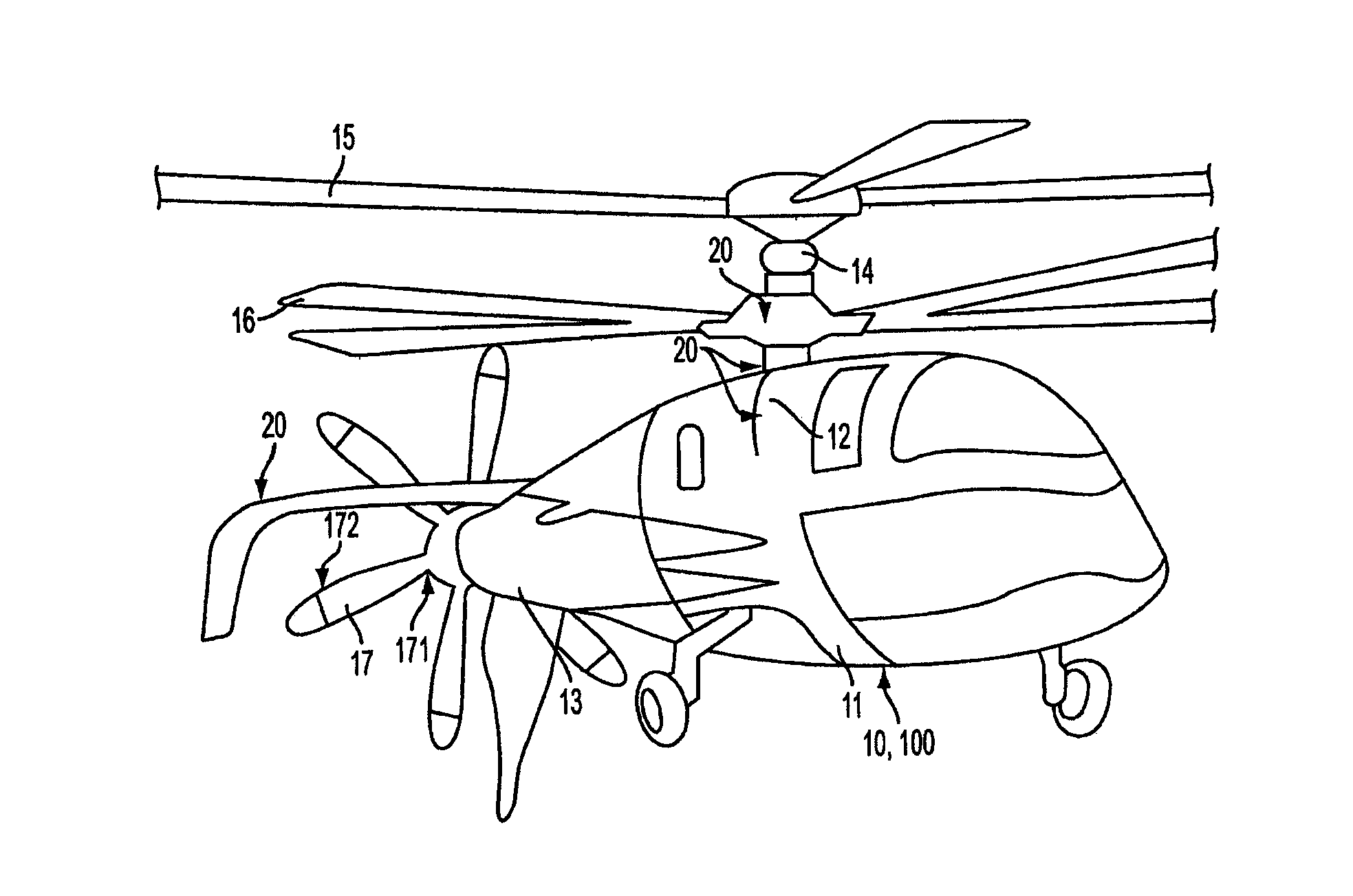
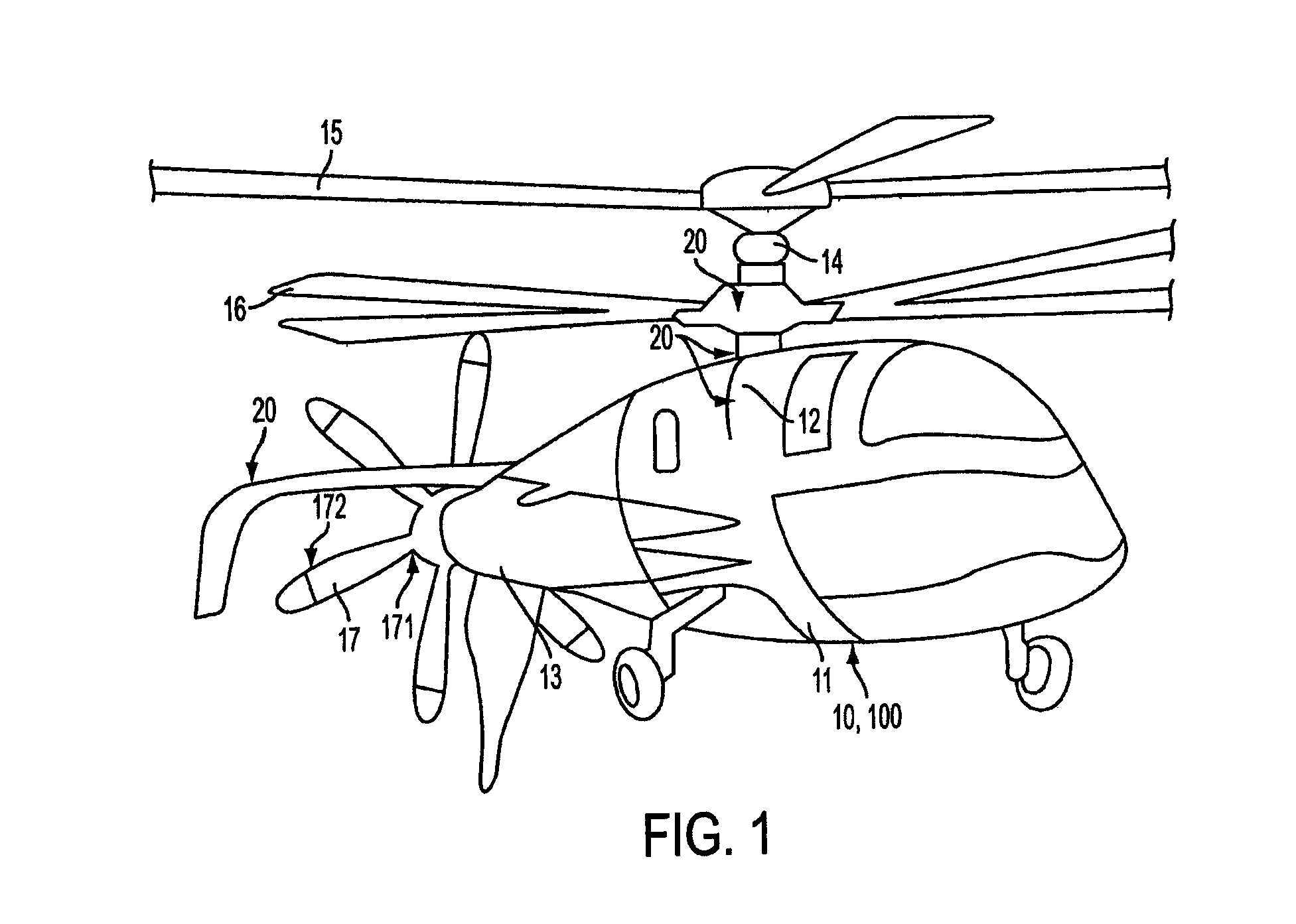
[0018]With reference to FIG. 1, a rotormachine 10 is provided. The rotormachine 10 includes a fuselage 11 that is formed to define an interior cabin in which a pilot and passengers may be situated. The fuselage 11 includes a rotor section 12 at a top portion thereof and a tail section 13 at a trailing end thereof. The rotor section 12 is supportive of a main rotor shaft 14 that is rotatable about its longitudinal axis relative to the fuselage 11. The main rotor shaft 14 is respectively coupled to coaxial main rotor blades 15 and 16, which rotate with the main rotor shaft 14 to provide a lift force for the rotormachine 10. The tail section 13 is supportive of a propeller shaft (not shown) that is rotatable about a longitudinal axis thereof relative to the fuselage 11 and in a plane defined transversely with respect to a rotational plane of the main rotor shaft 14. The propeller shaft is coupled to a pusher (or propulsor) propeller 17, which rotates with the propeller shaft, to provid...


PUM


Abstract

A boundary layer ingesting (BLI) blade having a span is provided and includes a root section connectable to a hub, a tip section disposable at a distance from the hub and having a pitch and a body extending in a spanwise dimension from the root section to the tip section. The root section has a local pitch from the root section to about a 70% span location, which is less than the pitch at the tip section, to thereby reduce local angles of attack in a boundary layer region defined in and around the root section.

Description

BACKGROUND OF THE INVENTION[0001]The subject matter disclosed herein relates to a boundary layer ingesting blade and, more particularly, to a boundary layer ingesting blade of a compound helicopter.[0002]Propellers are often designed in isolation where ideal inflow conditions are assumed, such as a case in which the free stream airflow velocity upstream of the propeller is uniform and constant. This assumption is often useful since most propellers are used in a tractor configuration where they are disposed upstream of fuselage or a wing and the assumption relatively closely approximates the physics of a tractor propeller. When a propulsor propeller or fan is placed in the wake of a body (i.e., fuselage, wing, strut, etc.), the propulsor propeller or fan is no-longer operating in its design environment and its performance will likely be degraded.BRIEF DESCRIPTION OF THE INVENTION[0003]According to one aspect of the invention, a boundary layer ingesting (BLI) blade having a span is pr...

Claims


Application Information

Patent Timeline
Patent Type & Authority Applications(United States)
IPC IPC(8): F01D5/14
CPCF01D5/14B64C11/18B64C27/82B64C2027/8236
Inventor MOFFITT, BLAKE ALMYTILLMAN, THOMAS G.WAKE, BRIAN E.MIN, BYUNG-YOUNGMATALANIS, CLAUDE G.
Owner SIKORSKY AIRCRAFT CORP
Why Eureka
Try Eureka