Pump condition monitoring and recovery

a technology of pump condition monitoring and recovery, applied in the field of fluid pumps, can solve the problems of preventing the operation of the vehicle by shutting down the fuel pump, damage to the motor, etc., and achieve the effect of reducing or eliminating the fault condition

Inactive Publication Date: 2015-06-04
NICHOLS PORTLAND LLC
View PDF8 Cites 10 Cited by
  • Summary
  • Abstract
  • Description
  • Claims
  • Application Information

AI Technical Summary

Benefits of technology

[0007]When any of the above or other conditions are detected, the system may take appropriate action. For example, during a low voltage condition the system may command the pump to run at a reduced speed, thereby preventing a system shutdown and enabling system operation with limited power availability. Should a no load condition be detected, the system may increase pump speed to remove air from the system. If load does not increase within a prescribed time, then the system may be shut down. Regarding a high temperature condition, the system may run the pump at a reduced speed to protect mechanical and / or electronic components.
[0018]In one embodiment, wherein the controller is configured to monitor an actual temperature of at least one of the fluid pump, a fluid in the system, the actuator, or the controller, and upon the actual temperature exceeding a corresponding predetermined temperature, the controller is configured to command the actuator to reduce a speed of the fluid pump.
[0028]In one embodiment, the controller is configured to monitor an actual temperature of at least one of the fluid pump, a fluid in the system, the actuator, or the controller, and upon the actual temperature exceeding a corresponding predetermined threshold, the controller is configured to command the actuator to reduce a speed of the fluid pump.
[0030]According to one aspect of the invention, a method for controlling a fluid pump via an actuator coupled to the fluid pump includes: detecting an irregular condition of at least one of the fluid pump or the actuator, and upon detecting the irregular condition, modifying at least one operating parameter of the actuator to prevent the irregular condition from transitioning to a fault condition.

Problems solved by technology

Damage to the motor may result, however, if the motor is operated when the motor temperature falls outside the temperature range.
A problem with conventional control systems that shut down on the occurrence of a fault is that they prevent use of the system, which can be problematic in certain situations.
For example, if the fluid pump is a fuel pump for a vehicle, shutting down the fuel pump prevents operation of the vehicle.

Method used


Image

  • Pump condition monitoring and recovery
  • Pump condition monitoring and recovery
  • Pump condition monitoring and recovery

Examples


Embodiment Construction

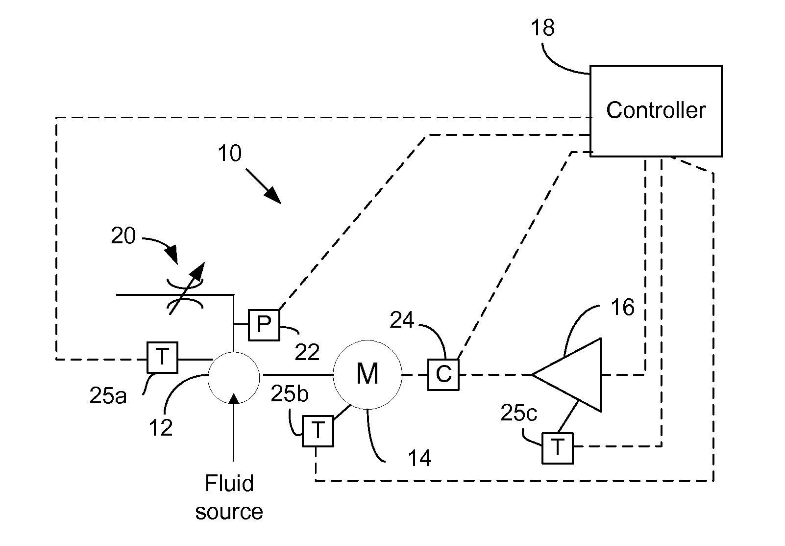
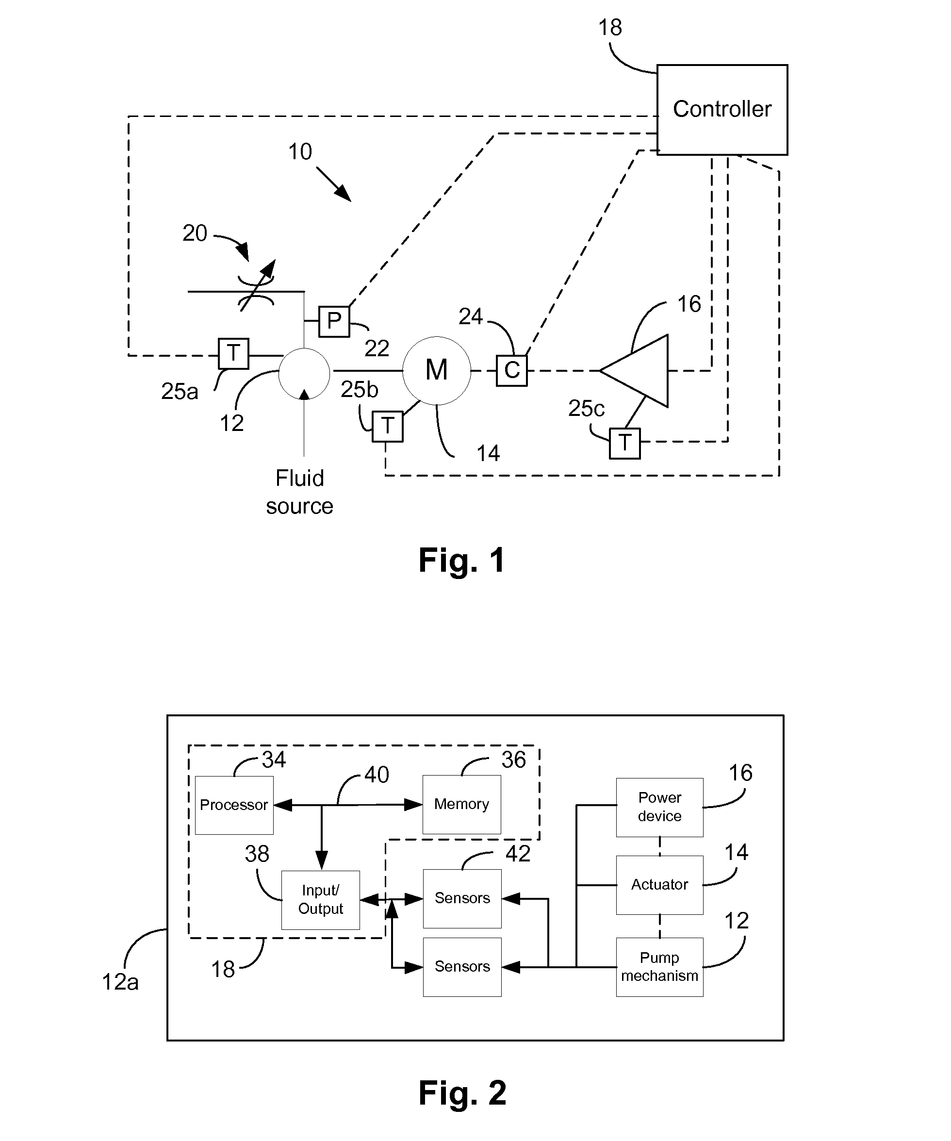
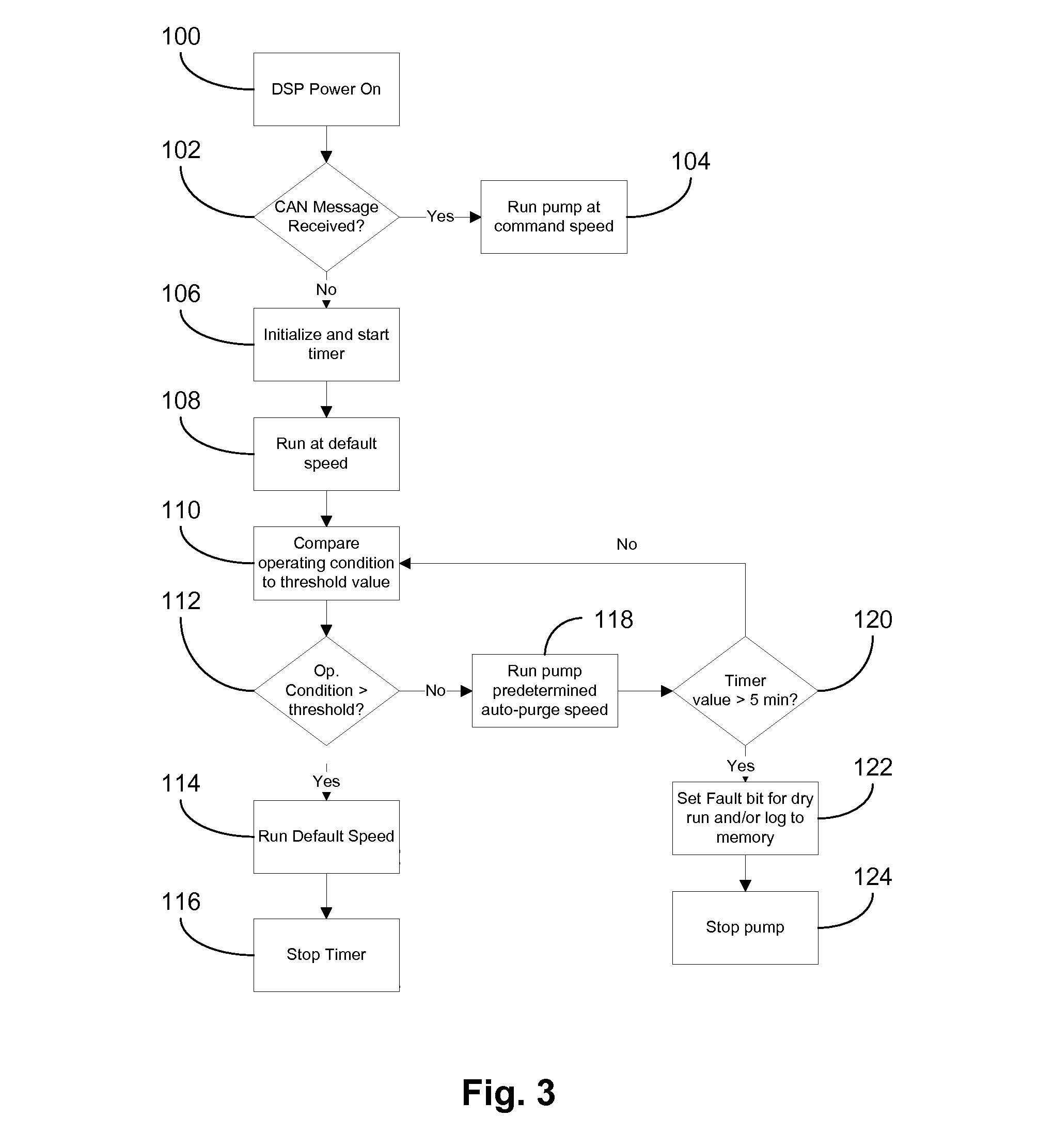
[0038]An apparatus, system and method for controlling a controlled element, such as a fluid pump (e.g., a fuel pump, water pump, oil pump, etc.) and the like, analyzes actual system data to determine the presence of an irregular condition (e.g., a potential fault condition). In the event an irregular condition is detected, certain actions may be taken to prevent occurrence of a fault condition and thus prevent system shutdown, thereby maintaining a level of operation yet minimizing the likelihood of component damage.

[0039]As used herein, the term “fault condition” is defined as an event triggered due to an operating characteristic of the system and / or a component of the system exceeding a prescribed fault threshold level. Continued operation of the system above the fault threshold level may result in system damage.

[0040]As used herein, the term “irregular condition” is defined as an event triggered due to an operating characteristic of the system and / or a component of the system exc...


PUM


Abstract

A fluid pumping system includes a fluid pump, an actuator coupled to said fluid pump, and a controller operatively coupled to the actuator. The controller is configured to detect an irregular condition of at least one of the fluid pump, the actuator or the controller, and upon detecting the irregular condition, modify at least one operating parameter of the actuator to prevent the irregular condition from transitioning to a fault condition.

Description

RELATED APPLICATION DATA[0001]This application claims priority of U.S. Provisional Application No. 61 / 911,505 filed on Dec. 4, 2013, which is incorporated herein by reference in its entirety.FIELD OF INVENTION[0002]The present invention relates to fluid pumps, and more particularly, to an apparatus, system and method for minimizing the occurrence of fault conditions that would otherwise shut down a fluid pump.BACKGROUND[0003]Control systems for controlling devices, such as electric motors, are well known in the art. Typically, a control system includes a main power component, e.g., a power module or the like that provides current and voltage to the motor, and a controller, e.g., a computer or other “smart” device that supervises system operation and provides control signals to the power module.[0004]Part of the supervisory function of the controller includes the detection of fault conditions. A fault condition typically refers to any condition that is not within a predefined operati...

Claims


Application Information

Patent Timeline
Patent Type & Authority Applications(United States)
IPC IPC(8): F04B49/06F04D15/02F04D27/00F04D15/00
CPCF04B49/065F04D15/0066F04D15/0281F04D27/008F04D15/0263F04D27/004F04D27/001F04D15/0254F04B49/06F04B49/08F04B49/10F04B2201/0801F04B2203/0201F04B2203/0202F04B2203/0205F04B2203/0209
Inventor DARAK, NICHOLASLESSARD, RANDY S.
Owner NICHOLS PORTLAND LLC
Why Eureka
Try Eureka