LED lamp

Inactive Publication Date: 2015-06-04
CHEN YU SYUAN
View PDF5 Cites 14 Cited by
  • Summary
  • Abstract
  • Description
  • Claims
  • Application Information

AI Technical Summary

Benefits of technology

[0020]According to the LED lamp provided by the present invention, the annular wall formed at the periphery of the sleeve opening of the light-pervious cover is able to be engaged with the heat conductive housing and the circuit board is able to be pressed at the same time. Comparing to prior art, the heat conductive housing and the light-pervious cover of the present invention

Problems solved by technology

As such, if the circuit board is fastened through an adhering means, the heat generated by the LEDs would soften the adhering gel and the circuit board may be released from the heat conductive partition plate due to the gravity, so the heat dissipation for the circuit board is poor and the circuit board

Method used


Image

  • LED lamp
  • LED lamp
  • LED lamp

Examples


Embodiment Construction

[0029]Preferred embodiments of the present invention will be described with reference to the drawings.

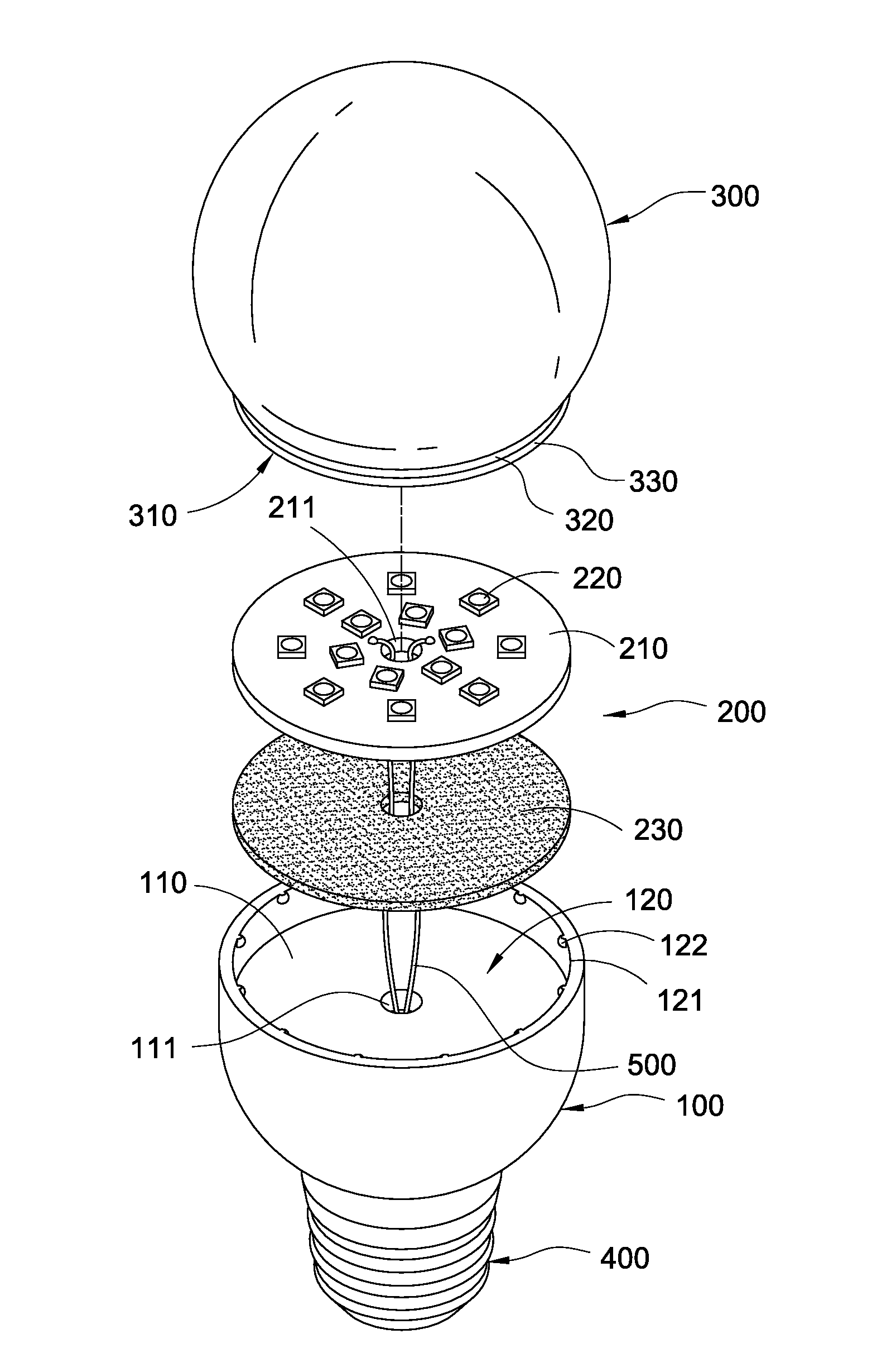
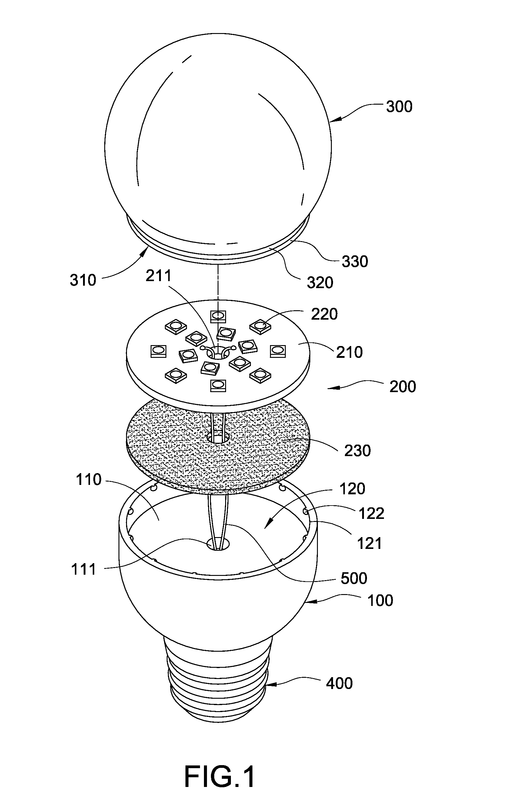
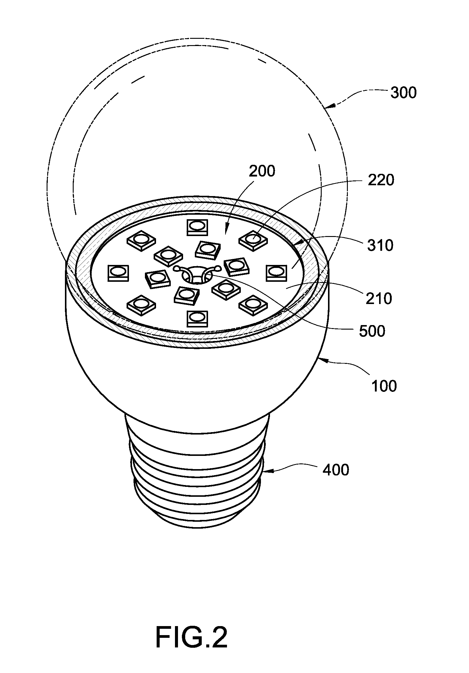
[0030]Please refer from FIG. 1 to FIG. 3, according to a first embodiment provided by the present invention, an LED lamp includes a heat conductive housing 100, a light source module 200, a light-pervious cover 300, a lamp header 400 and two wires 500.

[0031]According to this embodiment, the heat conductive housing 100 is preferably to be formed as a hollow tubular body made of a metal or other materials having relatively higher heat conductivity, and the interior of the heat conductive housing 100 is provided with a heat conductive partition plate 110, wherein the heat conductive partition plate 110 is preferably to be made of a metal or other materials having relatively higher heat conductivity and integrally formed with the heat conductive housing 100. The heat conductive partition plate 110 is formed with a penetrated hole 111, and the heat conductive partition plate 110 is serve...


PUM


Abstract

An LED lamp includes a heat conductive housing, a light source module and a light-pervious cover. The interior of the heat conductive housing is provided with a heat conductive partition plate capable of dividing the interior of the heat conductive housing thereby forming an accommodation space having a cavity at one end of the heat conductive housing. The light source module is disposed in the accommodation space and includes a circuit board and at least one LED disposed on the circuit board. The light-pervious cover is formed with a sleeve opening, and the periphery of the sleeve opening is protrudingly formed with an annular wall, the outer edge of the annular wall is mated and engaged with the inner edge of the cavity, thereby enabling the circuit board to be pressed by the annular wall so as to be tightly fastened on the heat conductive partition plate.

Description

BACKGROUND OF THE INVENTION[0001]1. Field of the Invention[0002]The present invention relates to an LED lamp, especially to an LED lamp having a stable structure and an advantage of easy assembly.[0003]2. Description of Related Art[0004]A conventional bulb mainly includes a housing formed with a cavity, and a heat conductive partition plate used for the purpose of heat conduction is disposed inside the cavity for allowing a circuit board to be installed thereon, and a plurality of LEDs are disposed on the circuit board. Generally, the circuit board is fastened on the heat conductive partition plate through a locking or adhering means.[0005]Because the bulb is often installed on a ceiling, the circuit board would be located at the bottom surface of the heat conductive partition plate. As such, if the circuit board is fastened through an adhering means, the heat generated by the LEDs would soften the adhering gel and the circuit board may be released from the heat conductive partition...

Claims


Application Information

Patent Timeline
IPC IPC(8): F21V15/01F21K99/00
CPCF21V15/011F21Y2101/02F21K9/30F21V3/00F21V19/004F21K9/232F21Y2115/10
Inventor CHEN, YU-SYUAN
Owner CHEN YU SYUAN
Why Eureka
Try Eureka