Driver device

a technology of a driver and a sensor is applied in the direction of control/drive circuit, transportation and packaging, cooling/ventilation arrangement, etc. it can solve the problems of increased large difference in heat stress on both sides so as to reduce the detection error of the rotation angle sensor and reduce the stress change along the substrate plane.

Active Publication Date: 2015-06-04
DENSO CORP
View PDF6 Cites 20 Cited by
  • Summary
  • Abstract
  • Description
  • Claims
  • Application Information

AI Technical Summary

Benefits of technology

[0013]According to the configuration described above, when the heat sink is deformed due to the temperature change, a deformation amount of the cylinder part is evenly distributed along the entire periphery. In other words, a difference of a deformation amount among different positions along the entire periphery is small. Therefore, the heat stress distribution applied to the substrate is evenly distributed along the substrate plane. In other words, the heat stress increases from a center part of the substrate toward the outer periphery portion thereof. Thereby, at the center part of the substrate where the rotation angle sensor is attached, stress change along the substrate plane decreases. In other words, the stress is a minimum at the center of the substrate, where the rotation angle sensor is positioned. Therefore, the magnitude of the stress applied to the rotation angle sensor is reduced to be as small as possible. Therefore, a detection error of the rotation angle sensor is reduced.

Problems solved by technology

Therefore, the substrate suffers from a heat stress that is caused by the difference between thermal expansion coefficients of two different materials when the temperature environment changes.
More specifically, there may be a big difference of heat stresses arising on both sides of the rotation angle sensor.
Thus, the stress applied on the rotation angle sensor increases due to such a big difference of heat stresses, thereby, causing an increased detection error of the rotation angle sensor.

Method used


Image

  • Driver device
  • Driver device
  • Driver device

Examples


Embodiment Construction

[0022]Hereafter, one embodiment of the present disclosure is described based on the drawing.

One Embodiment

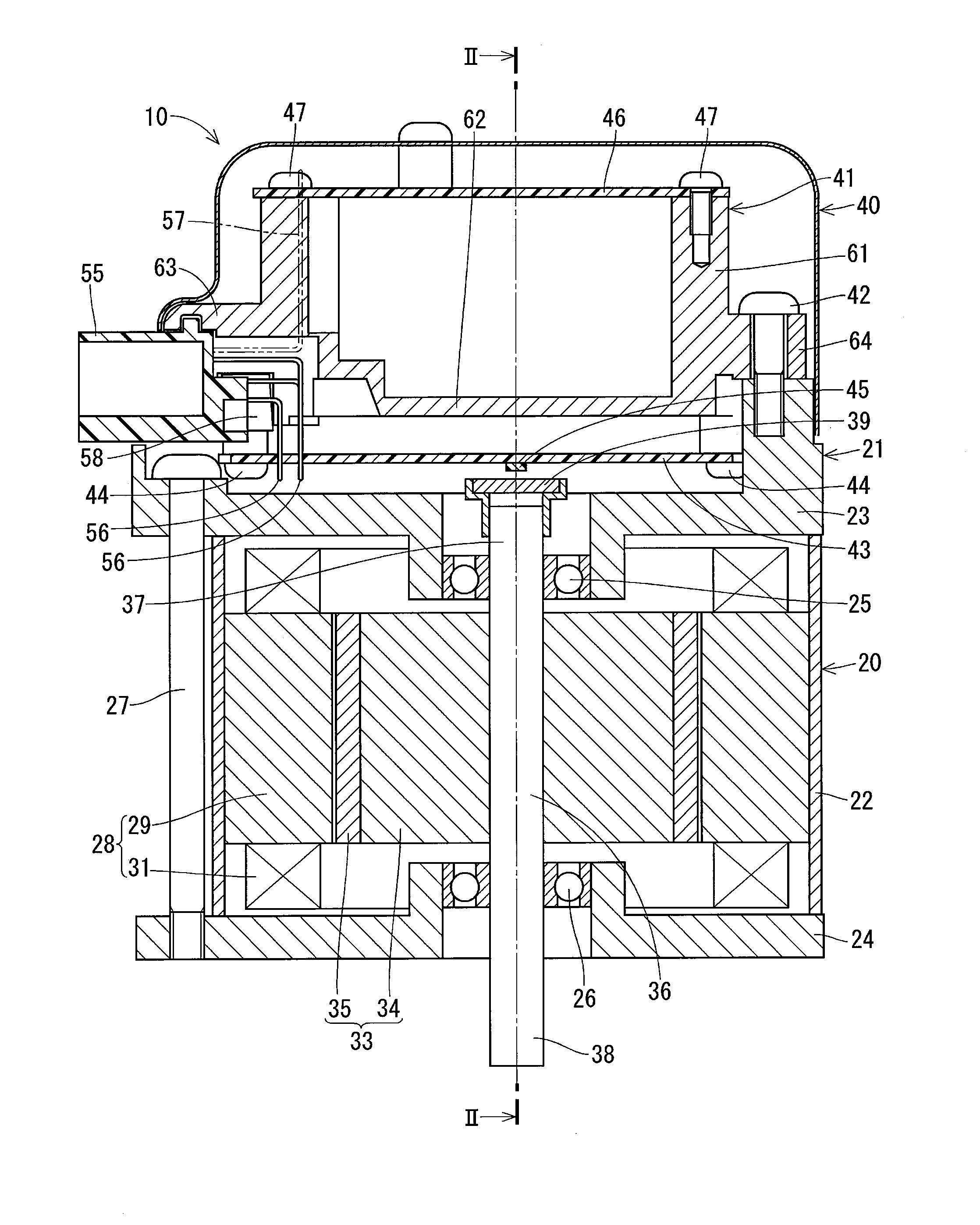
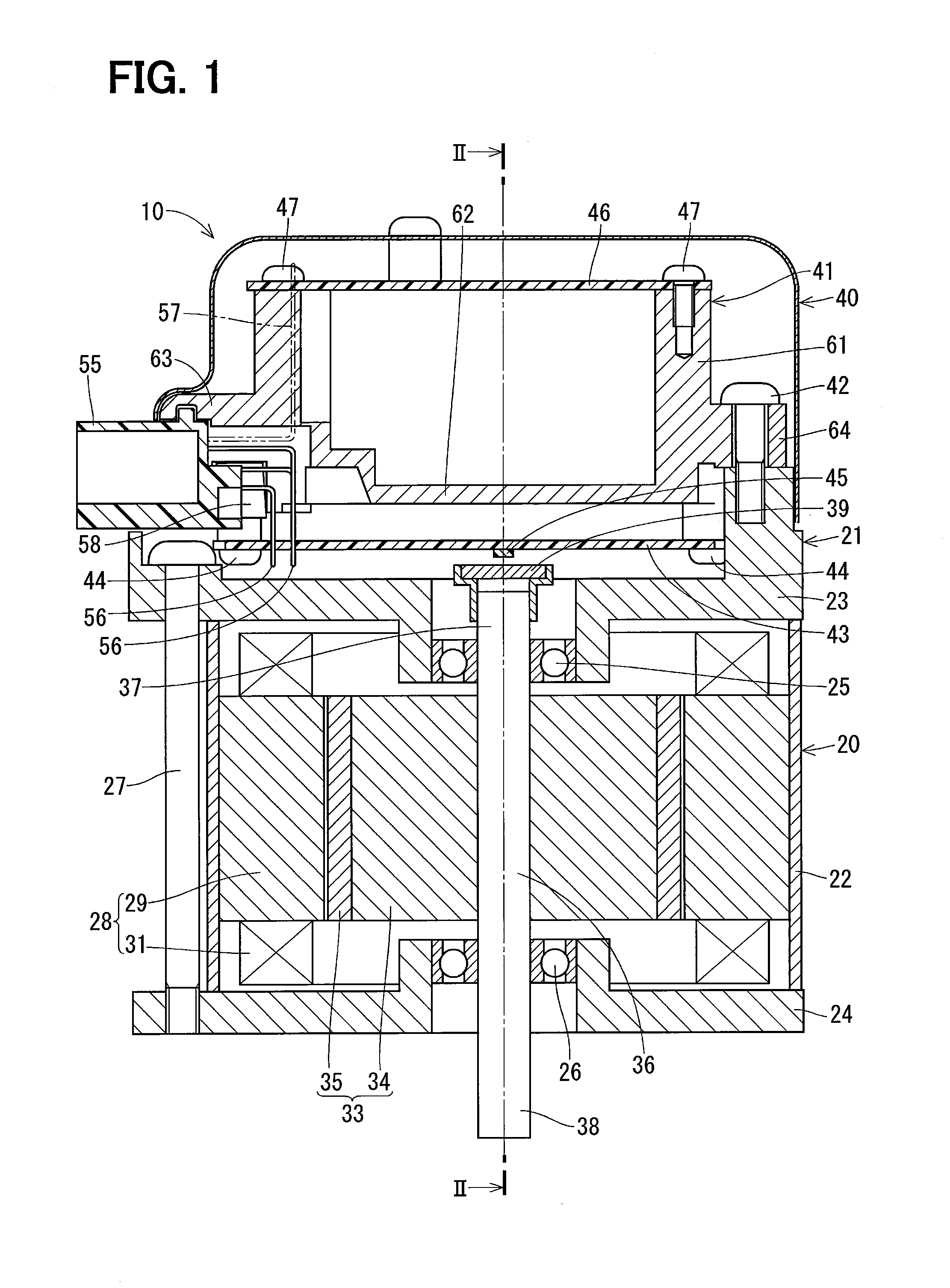
[0023]The driver device in one embodiment of the present disclosure is used for an electric power steering device of vehicles, for example. As shown in FIG. 1, a driver device 10 is an integral type driver device in which a motor 20 and a control unit 40 controlling the motor 20 are combined to have one body.

Configuration of an Entire Driver Device

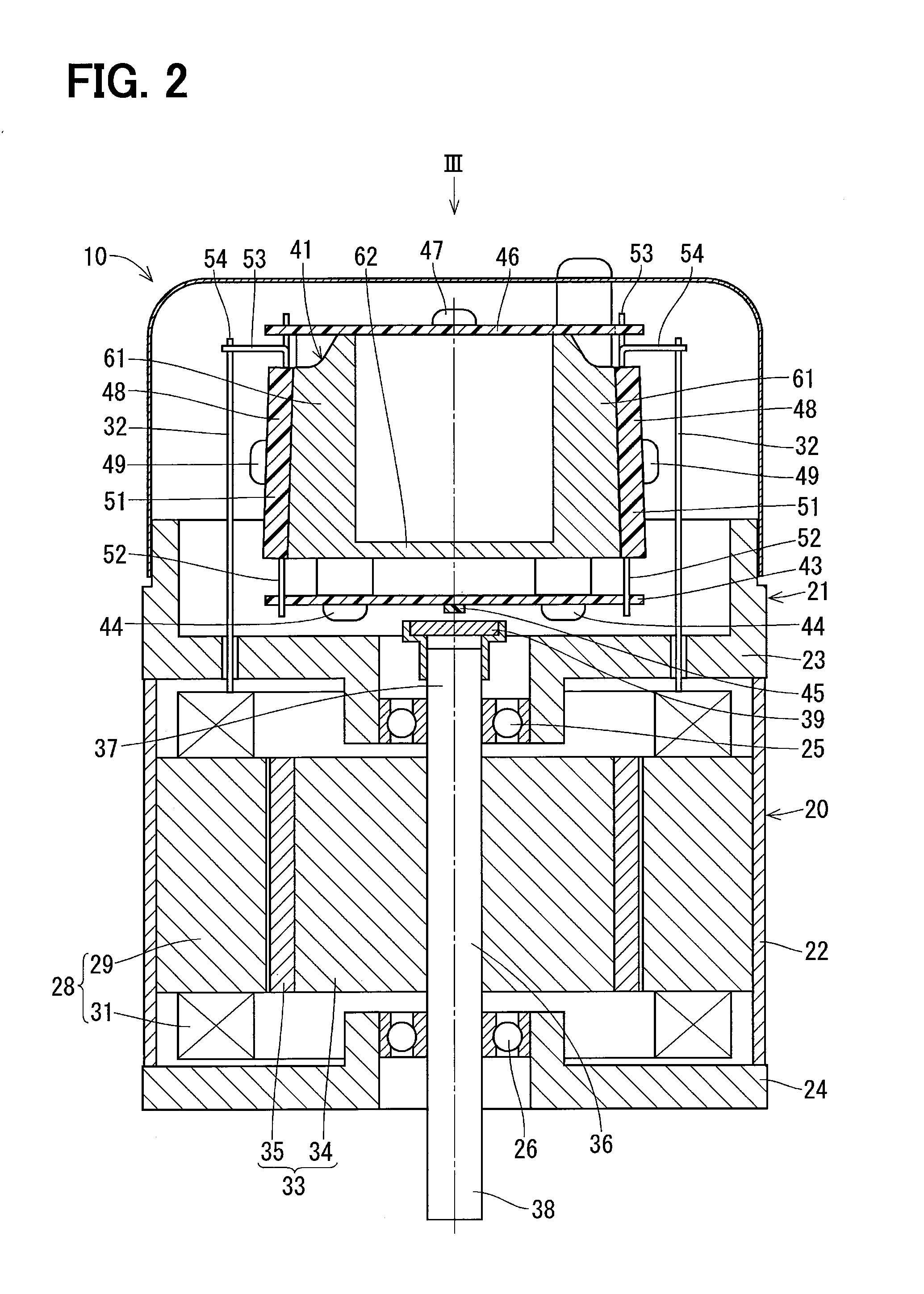
[0024]First, the entire configuration of the driver device 10 is described with reference to FIG. 1 and FIG. 2.

[0025](Motor)

[0026]The motor 20 is provided with a housing 21, a stator 28, a rotor 33, and a rotation shaft 36. In the present embodiment, the motor 20 is a three-phase brushless motor.

[0027]The housing 21 includes a case 22, a first frame 23, and a second frame 24. The case 22 is a cylinder shape member which consists of a soft magnetic material. The first frame 23 is disposed to cover one end part of the case 22. At the ce...


PUM


Abstract

In a driver device, a controller substrate has a center part on which a rotation angle sensor is attached and an outer periphery portion which is fixed onto a heat sink. The heat sink has a cylinder part extending in an axial direction of the rotation shaft to contact the outer periphery portion of the controller substrate. The cylinder part of the heat sink is continuously formed along an entire periphery and has the same height at all portions. Such configuration provides an even deformation distribution of the cylinder part due to a temperature change, thereby reducing unevenness of heat stress distribution along a substrate plane and decreasing stress applied to the sensor, which facilitates a reduction of a detection error of the sensor.

Description

CROSS REFERENCE TO RELATED APPLICATION[0001]The present application is based on and claims the benefit of priority of Japanese Patent Application No. 2013-247469, filed on Nov. 29, 2013, the disclosure of which is incorporated herein by reference.TECHNICAL FIELD The present disclosure generally relates to a driver device utilizing a motor.BACKGROUND INFORMATION[0002]Conventionally, a driver device having a motor and a control unit in one body is known. The control unit includes a rotation angle sensor for detecting a rotation angle of the motor and a semiconductor module having a switching element for switching the power supply to the winding of the stator of the motor. For example, in a patent document 1 (i.e., Japanese Patent Laid-Open No. 2012-152091), a semiconductor module is fixed to a heat sink, and the rotation angle sensor is attached to a substrate that is attached to the heat sink. The heat sink is disposed on an extension of an end part of a rotation shaft of the motor, ...

Claims


Application Information

Patent Timeline
Patent Type & Authority Applications(United States)
IPC IPC(8): H02K9/22H02K11/00
CPCH02K11/0015H02K9/22B62D5/0406H02K11/215H02K11/33H02K9/227
Inventor MATSUO, YASUFUMIYAMASAKI, MASASHI
Owner DENSO CORP
Why Eureka
Try Eureka