Distal balloon impedance and temperature recording to monitor pulmonary vein ablation and occlusion

a technology which is applied in the field of pulmonary vein ablation and temperature recording, can solve the problems of insufficient electrical isolation of reversible lesions, low temperature of cryoballoons, and insufficient creation of reversible lesions, so as to achieve real-time and accurate assessment and monitoring, and accurately monitor the formation of lesions

Active Publication Date: 2015-06-11
MEDTRONIC CRYOCATH LP
View PDF1 Cites 40 Cited by
  • Summary
  • Abstract
  • Description
  • Claims
  • Application Information

AI Technical Summary

Benefits of technology

[0010]The present invention advantageously provides a cryoablation method, system, and device that allows for real-time and accurate assessment and monitoring of PV ablation and occlusion without the need for expensive imaging systems and without patient exposure to radiation. The present invention further provides a means for using ice formation as an indicator of the presence and/or quality of PV ablation. The present invention also provides a cryoablation system and method that may accurately monitor lesion formation in real time, based on changes in the impedance measurements. A method of assessing lesion quality in pulmonary vein ostium tissue may include recording a first set of impedance measurements from an electrode on a balloon catheter having a treatment element at a distal portion, recording a second set of impedance measurements from the electrode, determining a first impedance slope using the first set of impedance measurements and determining a second impedance slope using the second set of impedance measurements, comparing the first slope to a first reference slope and the second slope to a second reference slope, and determining whether the balloon catheter is creating a permanent lesion in tissue surrounding the pulmonary vein (for example, a pulmonary vein antrum and/or ostium) based on the comparison of the first slope to the first reference slope and the second slope the second reference slope. Depending on the determination, the treatment element of the balloon catheter may be repositioned if lesion quality is poor (that is, if a permanent lesion is not being created in the tissue surrounding the pulmonary vein, such as pulmonary vein ostium tissue). The method may also include recording a set of temperature measurements and comparing the set of temperature measurements to the first slope and second slope of impedance measurements and comparing the set of temperature measurements to a reference temperature. The set of temperature measurements may be recorded from a thermocouple on the balloon catheter or the first electrode. The electrode may be located distal to the treatment element, such as at a location immediately distal to the

Problems solved by technology

The creation of reversible lesions may not be sufficient to achieve electrical isolation and, as a result, atrial fibrillation may be likely to reoccur.
Additionally, even if the PV is completely occluded, suboptimal operation of the cryoablation system may result in cryoballoon temperatures that are not low enough, or not applied for a sufficient amount of time, to create permanent lesions in the target tissue.
This method not only nece

Method used


Image

  • Distal balloon impedance and temperature recording to monitor pulmonary vein ablation and occlusion
  • Distal balloon impedance and temperature recording to monitor pulmonary vein ablation and occlusion
  • Distal balloon impedance and temperature recording to monitor pulmonary vein ablation and occlusion

Examples


first embodiment

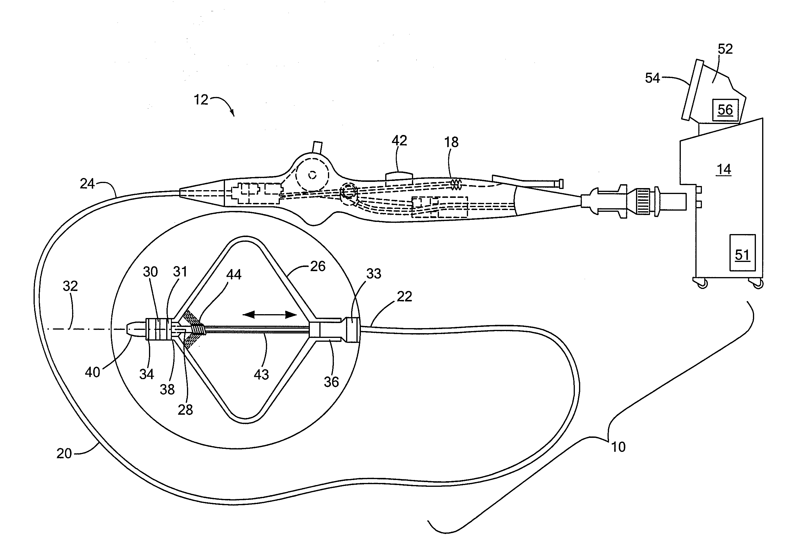
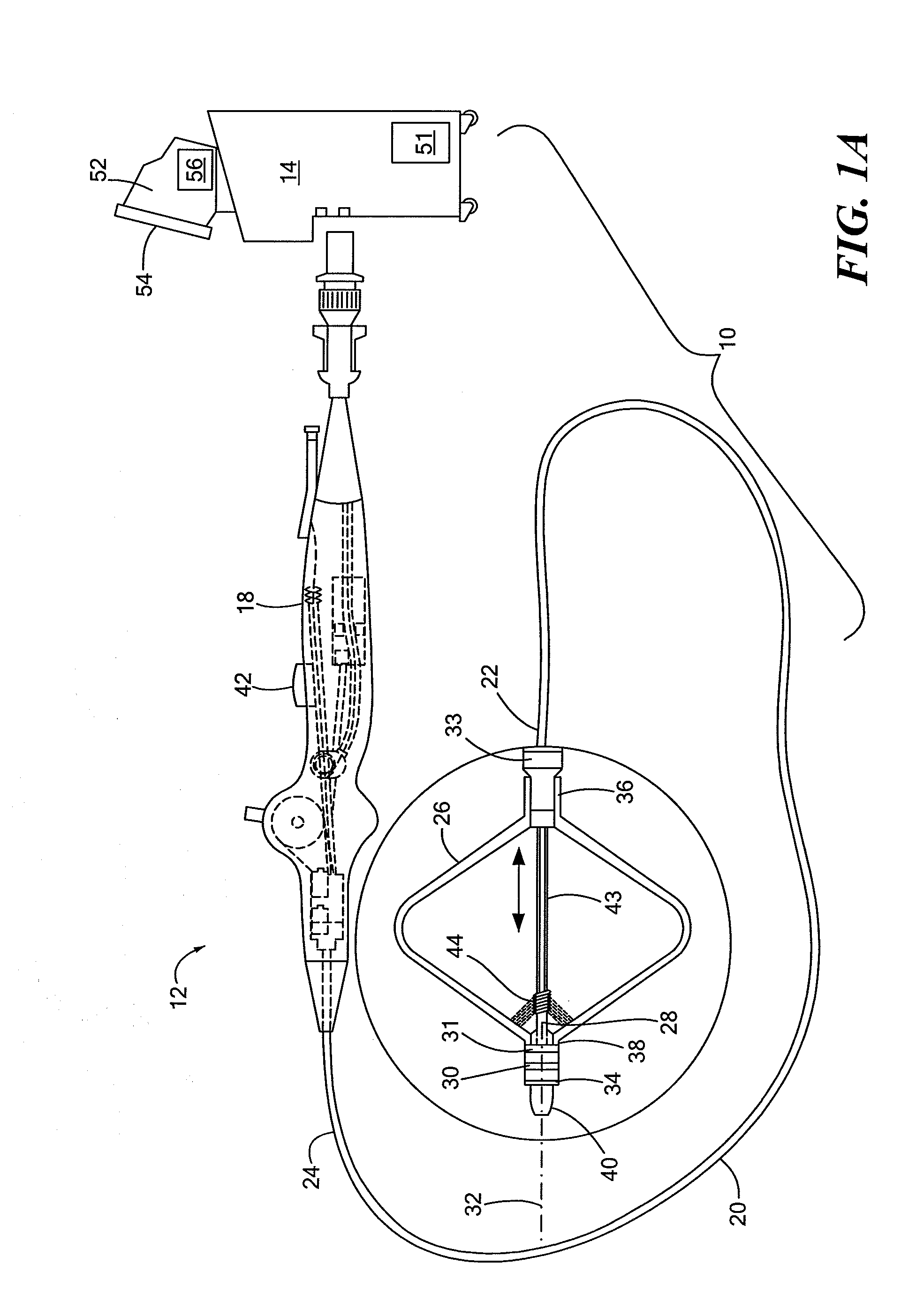
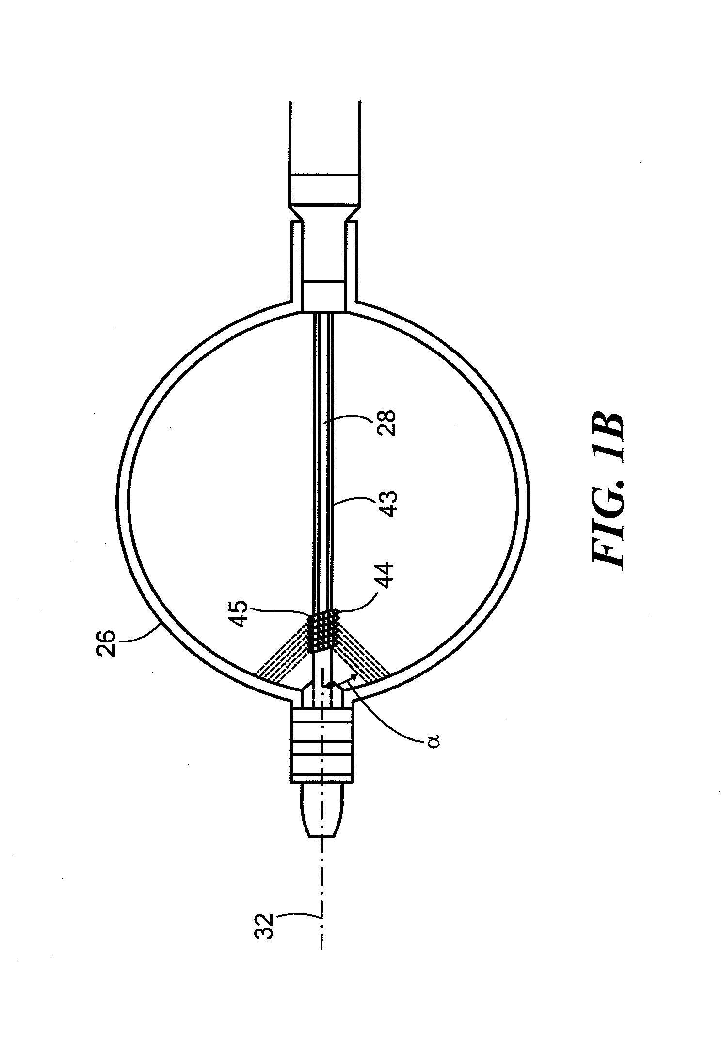
[0034]Referring now to FIG. 2, a close-up view of the distal portion of the cryoballoon catheter is shown. As shown and described in FIGS. 1A and 1B, the cryotreatment device 12 may include one or more distal electrodes 30 and one or more proximal electrodes 31. The device 12 may further include a reference electrode 33 and one or more thermocouples 34 if the electrodes 30, 31 are not configured to measure temperature. The electrodes 30, 31, 33 may be composed of an electrically conductive material suitable for sensing impedance and, optionally, temperature. In the embodiment shown in FIGS. 1A-2, both electrodes 30, 31 and thermocouple 34 may be located distal to the cryoballoon 26. Electrodes 30, 31, 33 and thermocouple 34 may be coupled to, affixed to, disposed about, integrated with, or otherwise located on a distal portion of the device 12. The proximal electrode 31 may be located immediately distal to the cryoballoon 26, such as on the shaft distal portion 40. For example, the ...

second embodiment

[0036]Referring now to FIG. 4, a close-up view of the distal portion of a cryoballoon catheter is shown. The embodiment shown in FIG. 4 is generally similar to those shown in FIGS. 1A-3. Like the embodiment shown in FIGS. 1A-3, the cryotreatment device 12 shown in FIG. 4 may include a proximal electrode 31 that is located proximal to the cryoballoon 26. Instead of a distal electrode 30, however, the device 12 may include a plurality of discrete electrodes 58A, 58B, 58C, . . . radially disposed about the shaft distal portion 40 immediately distal to the cryoballoon 26. For example, each electrode 58 may be radially spaced about the longitudinal axis of the device and may be adjacent to or may abut the cryoballoon 26. Each electrode 58 may be monitored individually, allowing the user and / or console 14 to evaluate the symmetry of the impedance rise and therefore the ice formation. For example, a small leak of blood form the PV past one side of the cryoballoon 26 may result in a slower ...


PUM


Abstract

A cryoablation method, system, and device that allows for real-time and accurate assessment and monitoring of PV occlusion and lesion formation without the need for expensive imaging systems and without patient exposure to radiation. The system includes a cryoballoon catheter with a cryoballoon, a distal electrode, a proximal electrode, and a temperature sensor. Impedance measurements recorded by the electrodes may be used to predict ice formation, quality of pulmonary vein occlusion, and lesion formation.

Description

CROSS-REFERENCE TO RELATED APPLICATION[0001]This application is related to and claims priority to U.S. Provisional Patent Application Ser. No. 61 / 912,991, filed Dec. 6, 2013, entitled DISTAL BALLOON IMPEDANCE AND TEMPERATURE RECORDING TO MONITOR PULMONARY VEIN OCCLUSION, the entirety of which is incorporated herein by reference.STATEMENT REGARDING FEDERALLY SPONSORED RESEARCH OR DEVELOPMENT[0002]n / aFIELD OF THE INVENTION[0003]The present invention relates to a cryoablation method, system, and device that allows for real-time and accurate assessment and monitoring of ice formation during pulmonary vein ablation using impedance measurements recorded by a distal electrode and a proximal electrode coupled to a cryotreatment device.BACKGROUND OF THE INVENTION[0004]A cardiac arrhythmia is a condition in which the heart's normal rhythm is disrupted. Certain types of cardiac arrhythmias, including ventricular tachycardia and atrial fibrillation, may be treated by ablation (for example, radi...

Claims


Application Information

Patent Timeline
IPC IPC(8): A61B18/02
CPCA61B18/02A61B2018/0022A61B2018/00404A61B2018/00875A61B2018/0268A61B2018/00684A61B2018/00577A61B2018/0212A61B2018/00821
Inventor AVITALL, BOAZCONDIE, CATHERINE R.
Owner MEDTRONIC CRYOCATH LP
Why Eureka
Try Eureka