Method for changing the software in the memory of an electronic control unit

a technology of electronic control unit and software, applied in the direction of data conversion, memory adressing/allocation/relocation, instruments, etc., can solve the problems of time-consuming and inability to always achieve the

Inactive Publication Date: 2015-06-11
DSPACE DIGITAL SIGNAL PROCESSING & CONTROL ENG
View PDF4 Cites 13 Cited by
  • Summary
  • Abstract
  • Description
  • Claims
  • Application Information

AI Technical Summary

Benefits of technology

[0038]In this way the effect is achieved that no change in functionality whatever initially results from the activation; namely, the processor processes exactly the same program code after the activation as before the activation. If the said jump instruction is now stored at an address of the active overlay memory, the result is achieved that during the next execution of the program routine the processing by the processor is redirected to the bypass routine outside of the overlay memory. The actual switchover to the bypass routine here thus does not take place through the activation of the overlay functionality, but instead through the storage of the jump instruction at the first address in the assigned overlay memory area, which in turn preferably is performed by the software that runs on the computer connected to the control unit through the said interface
[0039]The invention can provide for multiple implementations of the storage of the bypass routine while taking into account the safe deactivation / activation of the overlay functionality for the program routine that is to be at least partially replaced.

Problems solved by technology

In practice, this cannot always be accomplished.
For example, the supplier of the control unit may not be willing to do so, or the necessity of bypassing a specific function is not identified until after the control unit has already been completed.
This is not only time-consuming (from several tens of seconds to minutes) and interrupts ongoing test series, but it also stresses the flash memory, which is physically capable of withstanding only a limited number of storage operations.

Method used


Image

  • Method for changing the software in the memory of an electronic control unit
  • Method for changing the software in the memory of an electronic control unit
  • Method for changing the software in the memory of an electronic control unit

Examples


Embodiment Construction

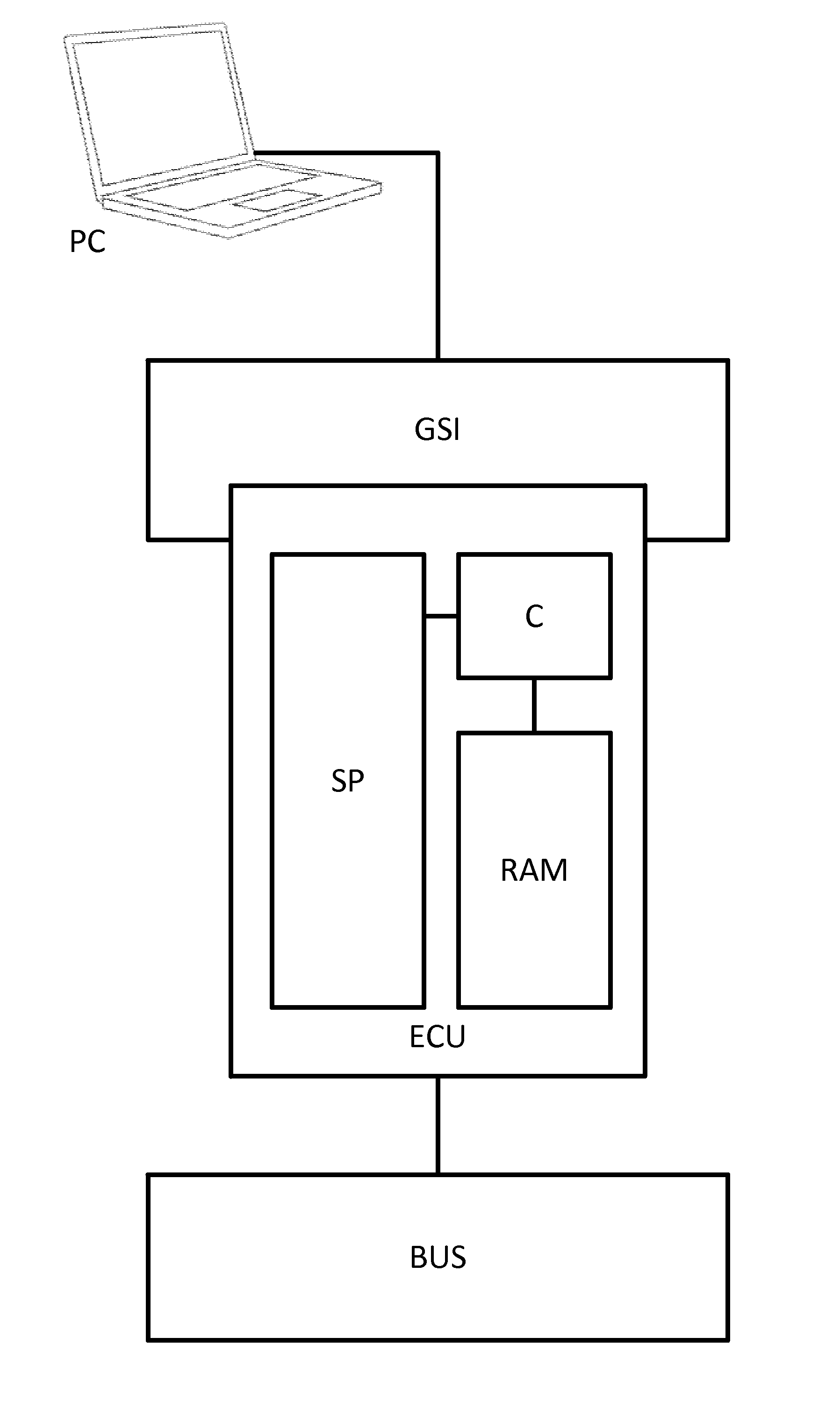
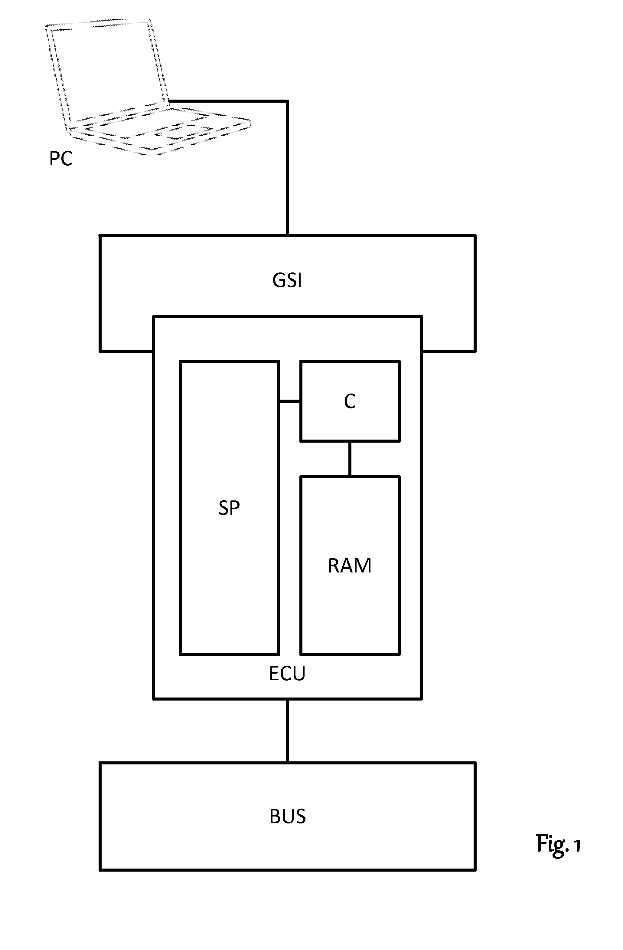
[0055]FIG. 1 outlines a typical bypassing scenario according to the conventional art. An electronic control unit ECU is being tested. This control unit has at least one read-only memory SP, usually a flash memory, a volatile working memory RAM, and a processor C that can access both memories. Located in the read-only memory SP is a computer program coded in machine language that determines the functionality of the control unit. If the control unit is intended for installation in an automobile, for example, the program can be a program for controlling an engine. The control unit also has interfaces. By means of these, it is able to accept data from sensors or other control units and evaluate them by the computer program stored on the read-only memory SP and executed by the processor C as well as to forward data produced by this program to other control units and actuators.

[0056]Preferably, ECU is a development control unit not intended to be installed in a completed product in mass p...


PUM


Abstract

A method for changing software in a memory of an electronic control unit, wherein each memory address from the overlay memory can be assigned to a memory address in the read-only memory by an assignment information item. During a run time of the control unit, at least a functional part of a bypass routine that is to at least partially replace an original program routine is stored in an address range in the overlay memory, or a jump instruction is stored in the overlay memory as the first part of a bypass routine that refers to a second part of the bypass routine that is stored in an address range accessible to the processor. To activate an overlay functionality the address and/or the address range of the overlay memory are assigned to an address or address range of the program routine to be replaced.

Description

[0001]This nonprovisional application claims priority to European Patent Application No. EP13005730.0, which was filed on Dec. 9, 2013, and which is herein incorporated by reference.BACKGROUND OF THE INVENTION[0002]1. Field of the Invention[0003]The present invention relates to a method for changing the software in the memory of an electronic control unit, wherein the memory includes at least one read-only memory with multiple original program routines stored therein that constitute at least a portion of the software and that are processed by at least one processor of the control unit, the memory has at least one working memory for storing volatile data, and the memory also has an overlay memory, from which each memory address can be assigned to a memory address in the read-only memory by an assignment information item, with the result that, when an overlay functionality is activated, instead of processing a program routine instruction at an address in the read-only memory, the proc...

Claims


Application Information

Patent Timeline
Patent Type & Authority Applications(United States)
IPC IPC(8): G06F12/06G06F13/24G06F9/445
CPCG06F12/0638G06F2212/202G06F13/24G06F8/65G06F8/66
Inventor DRESSLER, MARCHUFNAGEL, THORSTENKELLERS, BASTIAN
Owner DSPACE DIGITAL SIGNAL PROCESSING & CONTROL ENG
Why Eureka
Try Eureka