Solar array module system for generating electric power

Active Publication Date: 2015-06-11
SOLARWAT
View PDF10 Cites 4 Cited by
  • Summary
  • Abstract
  • Description
  • Claims
  • Application Information

AI Technical Summary

Benefits of technology

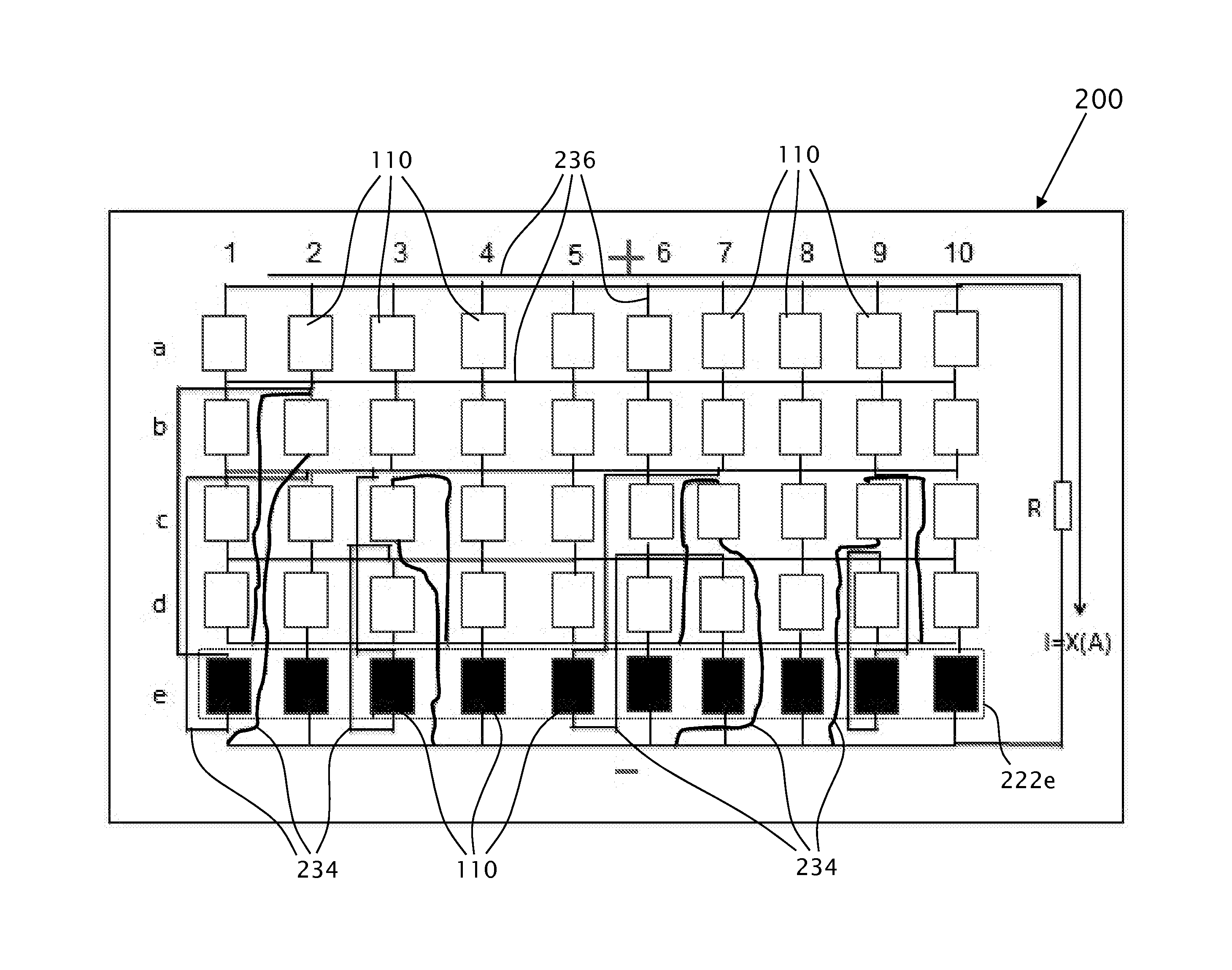
[0009]There is therefore a need and it would be advantageous to have one or more configurations of interconnectivity between solar cells 110, in a solar-array module having a crisscross network configuration, wherein such configuration facilitates maximization of the power generated by a solar-arra

Problems solved by technology

Such reduced functionality may be due to solar cell malfunction in one or more r

Method used


Image

  • Solar array module system for generating electric power
  • Solar array module system for generating electric power
  • Solar array module system for generating electric power

Examples


example

[0123]The output power of the solar-array module 1410 is 300 Watt;[0124]The output voltage of main DC / DC transformer / converter 1450 is 30 Volt (U4);[0125]The output voltage of second converter 1460 is 3 Volt (U3)[0126]The efficiency of main DC / DC transformer / converter 1450 is rated as 96%;[0127]The efficiency of second converter 1460 is rated as only 85%.

[0128]Hence, the output voltage of solar-array module 1300 is U4+U3, that is: 33V.

[0129]The total output power is computed as follow:

(300W*30V)*0.9633V+(300W*3V)*0.8533V=285W;

[0130]The efficiency of solar-array module 1400 is computed as follow:

285W*100300W=95%.

[0131]Hence, the total efficiency is reduced by 1% only.

[0132]In the described example, the voltage regulation is facilitated in the range of 0-10%. Referring back to FIG. 15, the exemplifies the influence of temperature fluctuation between 25° C. and 75° C., the knees of the 3 graphs are situated between 24V and 28V. At a temperature of 50° C., the knee is situated between 2...


PUM


Abstract

A modular solar panel system facilitated to maximize the power generation from a solar module, configured to maximize power generation from a plurality of solar cells under conditions of partial shade or light obstruction. The modular solar panel system includes a crisscross network configuration arrays, wherein the solar cells are often subjected to at least partial shading and wherein the present invention provides innovative configurations to minimize the damage inflicted by the shadows.

Description

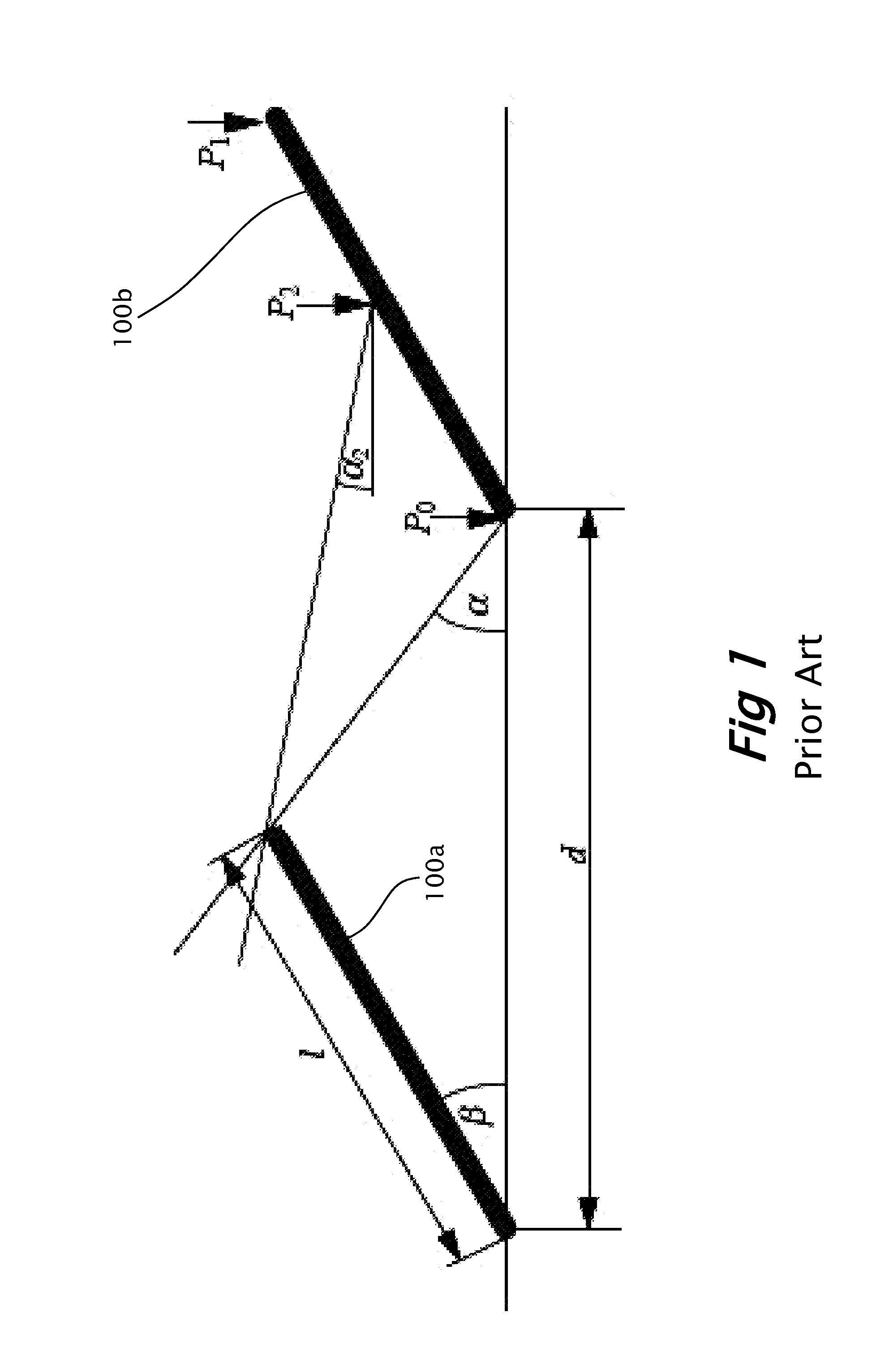
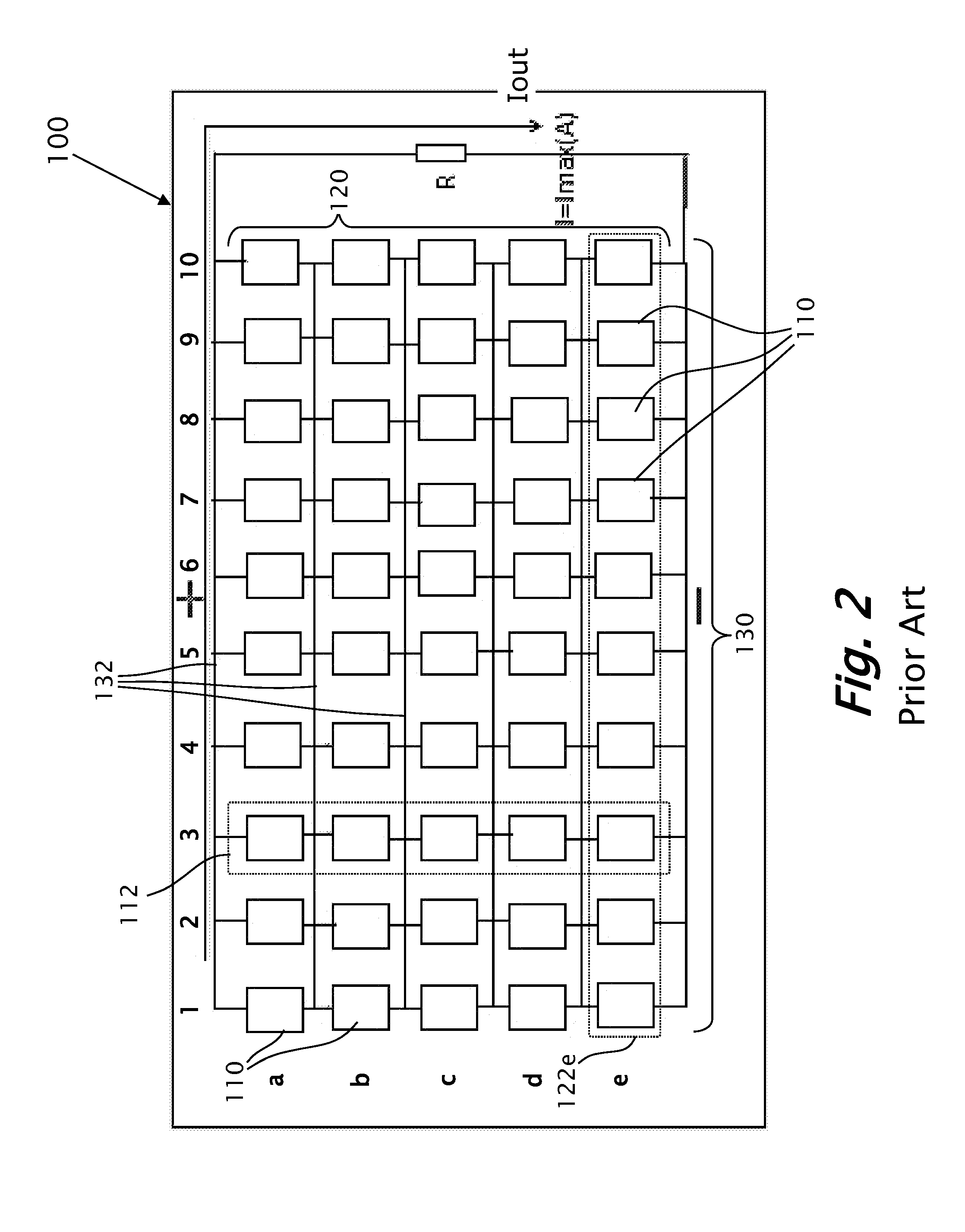
FIELD OF THE INVENTION[0001]The present invention relates to a solar array module system for generating electric-power and more particularly, to a solar array module system facilitated to maximize the power generation from a solar module, configured to reduce light obstruction and to maximize the power generation from a plurality of solar cells, interconnected in a matrix configuration.BACKGROUND OF THE INVENTION[0002]Photovoltaic cells have been widely used in a variety of applications to generate convenient electricity. Typically, a single solar cell produces an output voltage of around 0.5V, and a plurality of cells, typically Silicon based, is conventionally connected in series to provide higher voltage levels. The solar cells are typically interconnected in solar-arrays, as described in PCT Published Application No. WO / 2011 / 089607 filed on Jan. 23, 2011, by the same inventor as the instant application and which is owned in common, which is hereby incorporated by reference in it...

Claims


Application Information

Patent Timeline
IPC IPC(8): H01L31/02
CPCH01L31/02021H02J1/12Y02E10/50
Inventor VATELMACHER, BORISPAZ, GABI
Owner SOLARWAT
Why Eureka
Try Eureka