Touch-sensor structures and methods of forming the same

a technology of touch sensor and structure, applied in the field of touch device technology, can solve the problems of short or open issue between the sensing-electrode pattern of the touch sensor, failure to meet the needs of the user, and poor so as to prevent the second conductive layer from forming, the touch-sensing function of the conventional touch panel is often poor

Active Publication Date: 2015-06-11
TPK TOUCH SOLUTIONS (XIAMEN) INC
View PDF2 Cites 5 Cited by
  • Summary
  • Abstract
  • Description
  • Claims
  • Application Information

AI Technical Summary

Benefits of technology

[0007]The second ITO layer made of the non-crystalline indium tin oxide easily produces a re-crystalline phenomenon during the fabrication processes of conventional touch panels. The etching solution cannot completely etch the second ITO layer to form the required pattern. It causes a short or open issue to occur between the sensing-electrode patterns of the touch sensors. The touch-sensing function of conventional touch panels is often poor, or fails altogether. The

Problems solved by technology

It causes a short or open issue to occur between the sensing-electrode patterns of the touch sen

Method used


Image

  • Touch-sensor structures and methods of forming the same
  • Touch-sensor structures and methods of forming the same
  • Touch-sensor structures and methods of forming the same

Examples


Embodiment Construction

[0034]The following description is of the best-contemplated mode of carrying out the disclosure. This description is made for the purpose of illustrating the general principles of the disclosure and should not be taken in a limiting sense.

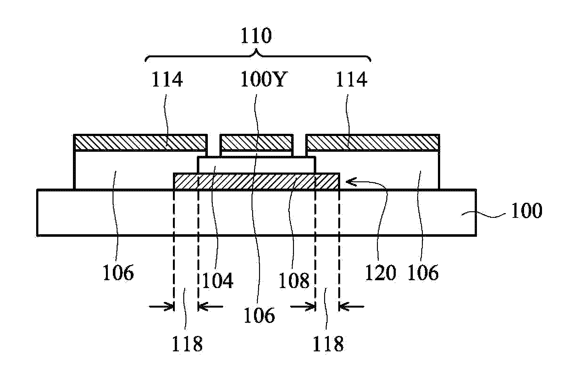
[0035]In the descriptions that follow, the orientations of “on”, “over”, “above”, “under” and “below” are used for representing the relationship between the relative positions of each element in the touch-sensor structures, and are not used to limit the disclosure.

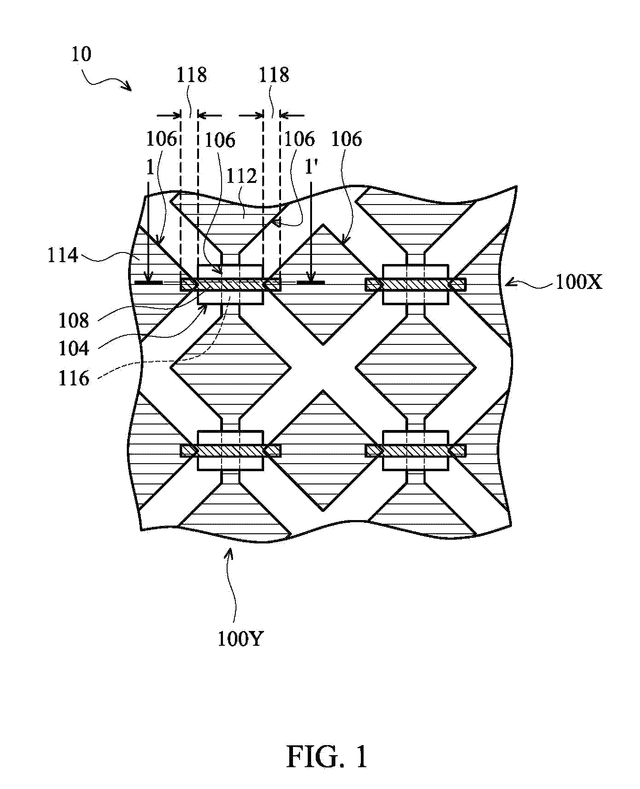
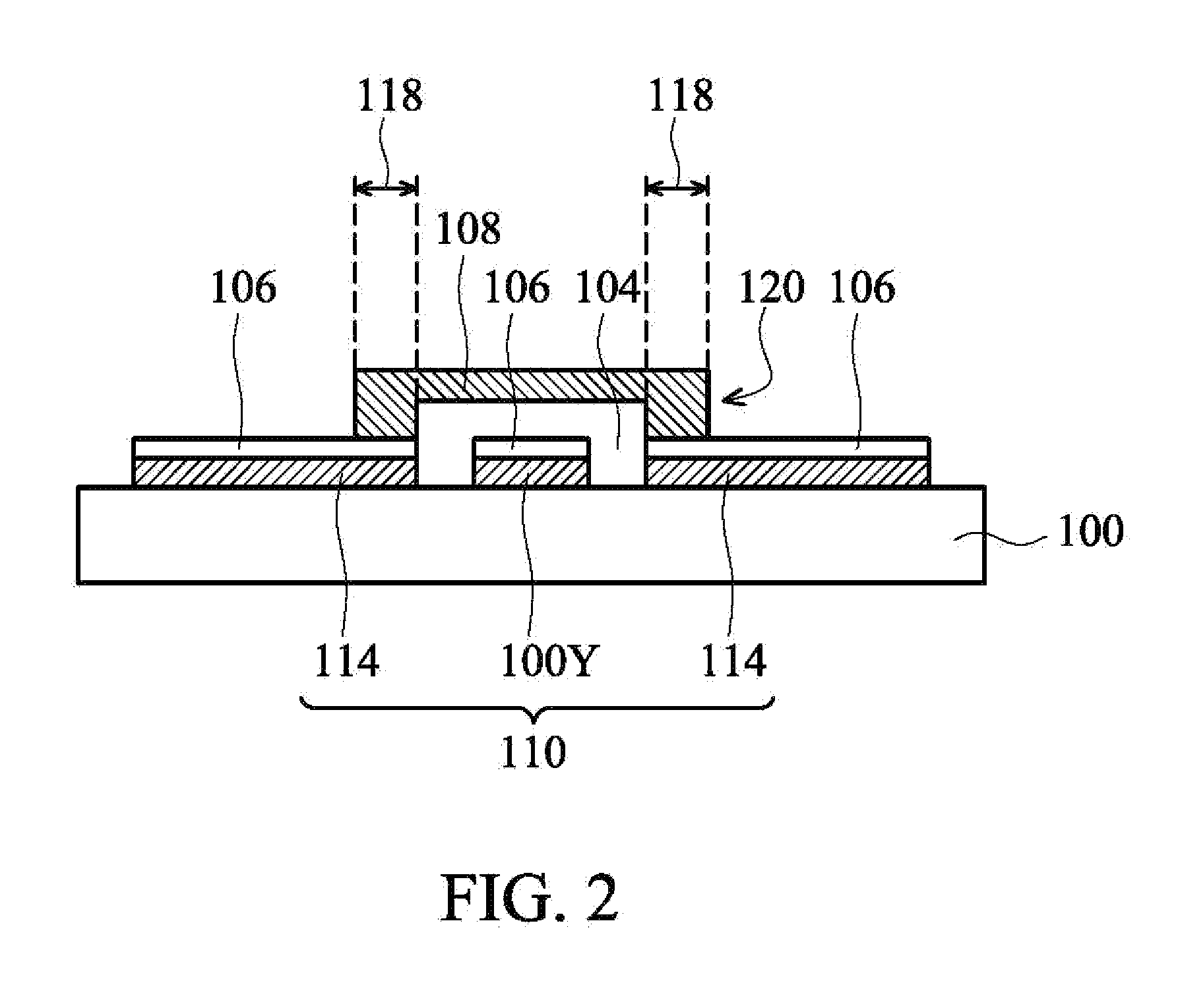
[0036]In the accompanying drawings, in order to clearly illustrate the characteristics of embodiments of the disclosure, each element in the touch-sensor structures may not be drawn to scale. Moreover, the embodiments of the touch-sensor structures and the methods of forming the same are described in an orientation in which the substrate is disposed at the bottom. However, in at least some touch panel applications, the touch-sensor structures are provided for users in an orientation in wh...


PUM


Abstract

A touch-sensor structure includes a first conductive layer, a second conductive layer, insulating isolation portions, and an intermediate conductive layer. The first conductive layer includes first conductive units, connection lines and second conductive units. Each connection line connects to two first conductive units. The second conductive layer includes bridge lines. Each bridge line is electrically connected to two second conductive units. The insulating isolation portion is disposed between the connection line and the bridge line. The intermediate conductive layer is at least disposed at an overlapping position between the bridge lines and the second conductive units to isolate the first conductive layer from the second conductive layer. The intermediate conductive layer electrically connects each bridge line to the corresponding second conductive units.

Description

BACKGROUND OF THE INVENTION[0001]This Application claims priority of the People's Republic of China Patent Application No. 201310657434.4, filed on Dec. 9, 2013, the entirety of which is incorporated by reference herein.[0002]1. Field of the Invention[0003]The disclosure relates to touch device technology, and in particular, to touch-sensor structures and methods of forming the same.[0004]2. Description of the Related Art[0005]Recently, touch panel techniques have been developed to be a main input method and have been popularly applied in various electronic products, such as mobile phones, personal digital assistants (PDA), and handheld personal computers. Touch sensors of a touch panel are usually formed from a first indium tin oxide (ITO) layer and a second ITO layer. The first. ITO layer forms a plurality of sensing-electrode patterns connecting with each other and arranged to form a plurality of columns, and a plurality of sensing-electrode patterns separated from each other and...

Claims


Application Information

Patent Timeline
IPC IPC(8): H03K17/96
CPCH03K17/9618H03K2217/96015H03K2017/9615G06F3/0443G06F3/0446G06F2203/04103G06F2203/04111
Inventor HSU, I-CHUNG
Owner TPK TOUCH SOLUTIONS (XIAMEN) INC
Why Eureka
Try Eureka