
Image pickup apparatus that displays image based on signal output from image pickup device, method of controlling the same, and storage medium

a technology of image pickup and image, applied in the direction of color signal processing circuits, color television details, television systems, etc., can solve the problems of increased power consumption, unnecessary waiting time, and reduced operability, and achieve the effect of improving the operability of the image pickup apparatus

Inactive Publication Date: 2015-06-11
CANON KK
View PDF2 Cites 23 Cited by
  • Summary
  • Abstract
  • Description
  • Claims
  • Application Information

AI Technical Summary

Benefits of technology

The present invention provides an image pickup apparatus that can improve operability and save power by starting and ending image pickup without stopping. Additionally, it can prevent degraded image quality and reduce power consumption while quickly and accurately focusing on a target.

Problems solved by technology

However, in this case, when changing the frame rate, unnecessary waiting time is generated, which may cause undesired reduction of operability.
However, in Japanese Patent Laid-Open Publication No. 2013-55589, during display of an object image on the image display section before photographing a still image, images are always simultaneously read out at the plurality of frame rates, which increases power consumption.
Further, if images are simultaneously read out at the plurality of frame rates by the operation of pressing the release button, unnecessary waiting time is generated in changing the control of the image pickup device, and time lag caused by the waiting time reduces the operability of the camera.
On the other hand, in Japanese Patent Laid-Open Publication No. 2009-171004, image pickup by the image pickup section is temporarily stopped and resumed according to instructions provided by a user's operation, and hence it is impossible to determine based on object information whether or not a temporary stop period is required.
As shown in FIG. 7, when the AF evaluation image is picked up, the frame rate is set to a higher rate than in the live view image pickup period, and hence a thinning ratio for reading by the image pickup device is increased, which inevitably degrades image quality.
Therefore, it is difficult to avoid uncomfortable feeling due to degradation and fluctuation of image quality of the live view image.
However, in the image pickup apparatus described in Japanese Patent Laid-Open Publication No. 2010-181751, when reading out the pixels, it is necessary to handle the focus detection pixels as defective pixels on the photographed image.
For this reason, taking into account image quality of e.g. a still image using all pixels, it is difficult to arrange the focus detection pixels at a high density in all areas of the image pickup device.
Therefore, it is difficult to perform AF control with high accuracy by covering a sufficient angle-of-view area only with the focus detection pixels, and to improve the AF control performance, it is necessary to use the contrast AF method using the image signals in combination with the phase difference AF method using the focus detection pixels.
In this case, in the contrast AF method, a time lag is generated due to the above-mentioned change of the manner of driving, and further, when degradation of image quality of the live view image is taken into account, the use of the phase difference AF method and the contrast AF method in combination makes it difficult to prevent a time lag from being generated, and image quality from being degraded.

Method used


Image

  • Image pickup apparatus that displays image based on signal output from image pickup device, method of controlling the same, and storage medium
  • Image pickup apparatus that displays image based on signal output from image pickup device, method of controlling the same, and storage medium
  • Image pickup apparatus that displays image based on signal output from image pickup device, method of controlling the same, and storage medium

Examples


first embodiment

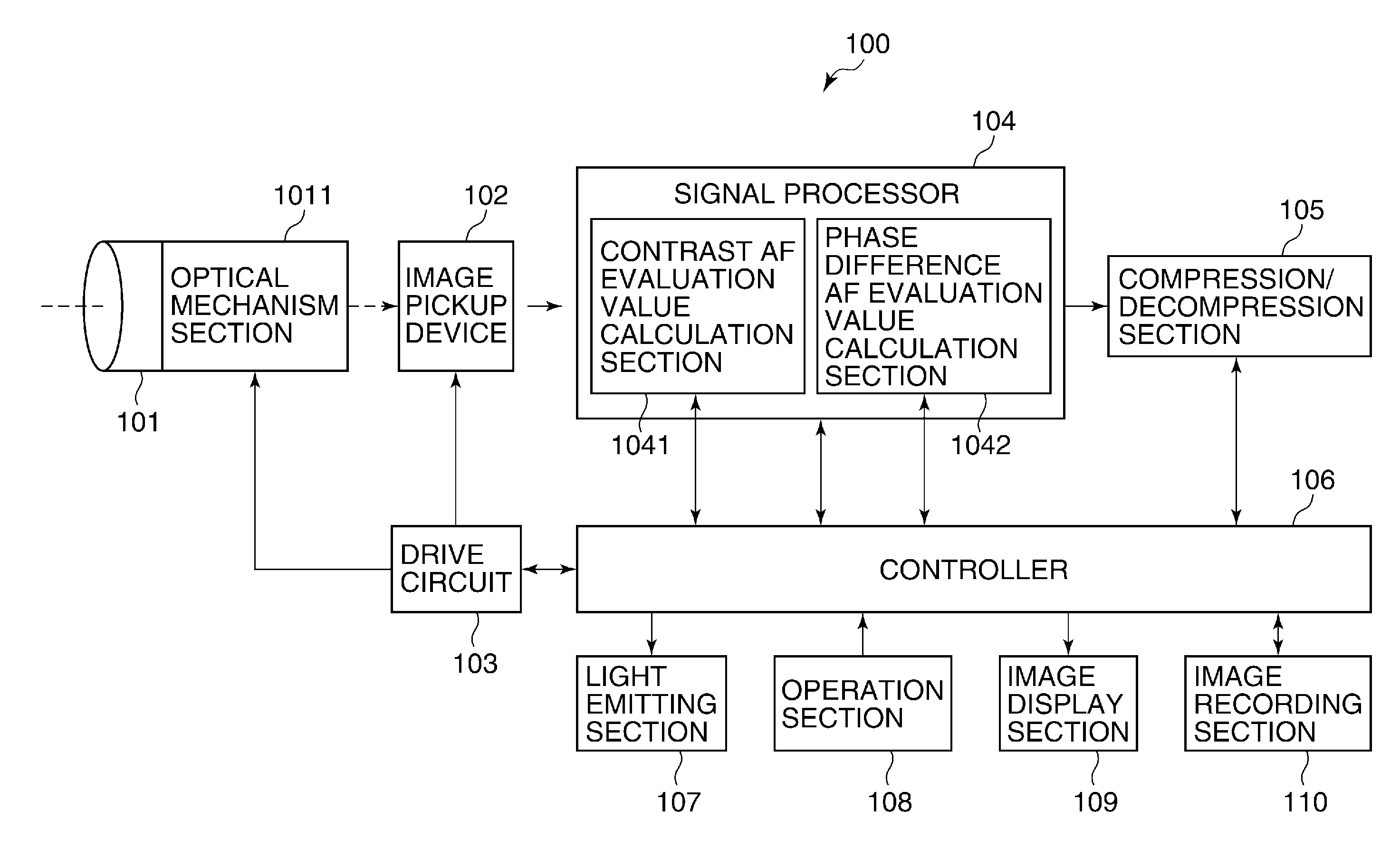
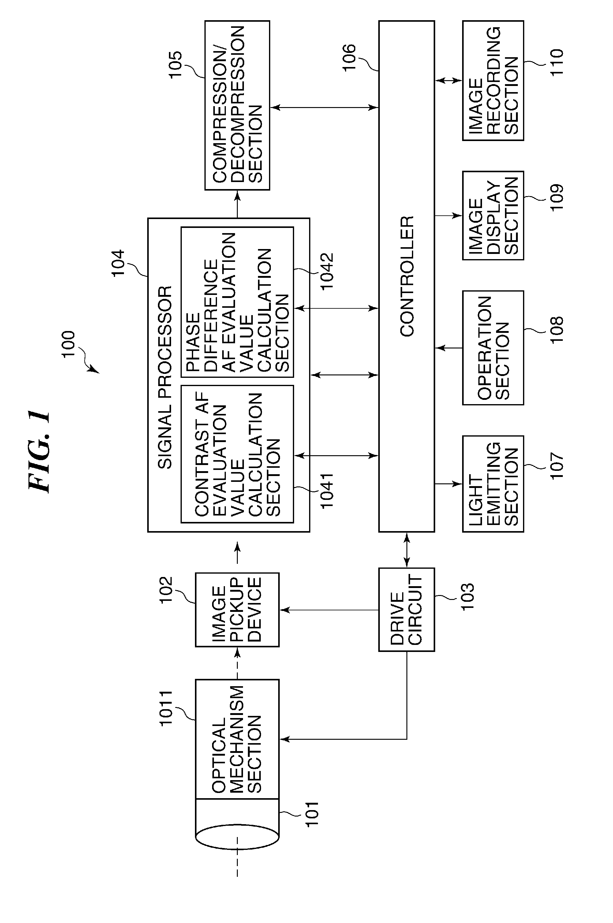
[0051]FIG. 1 is a block diagram of an image pickup apparatus according to the present invention.

[0052]The illustrated image pickup apparatus is, for example, a digital still camera with a moving image photographing function, or a video camera (hereinafter simply referred to as the camera). The camera, denoted by reference numeral 100, includes an optical lens barrel 101, an image pickup device 102, a drive circuit 103, a signal processor 104, a compression / decompression section 105, a controller 106, a light emitting section 107, an operation section 108, an image display section 109, and an image recording section 110.

[0053]The optical lens barrel 101 is comprised of a photographic lens unit (not shown, hereinafter simply referred to as the photographic lens) and an optical mechanism section 1011. The photographic lens collects light from an object on the image pickup device 102 (i.e. forms an optical image thereon).

[0054]Although not shown, the optical mechanism section 1011 inclu...


PUM


Abstract

An image pickup apparatus that makes it unnecessary to temporarily stop image pickup performed by an image pickup device to thereby improve operability of the image pickup apparatus, and achieves power saving. In an image pickup apparatus having an electronic viewfinder function, first image signals for live view are acquired by thinning read lines of an image pickup device, and second image signals for AF evaluation value calculation are acquired from the other read lines at a higher speed than the first image signals, for simultaneous output with the first image signals. Reading of the second image signals is started when the state of the object of image data changed or when one photographing mode is changed to another by a user's operation, and is terminated when a reading termination condition set in advance in association with the reading start condition is satisfied.

Description

BACKGROUND OF THE INVENTION[0001]1. Field of the Invention[0002]The present invention relates to an image pickup apparatus having an electronic viewfinder function, such as a digital still camera and a digital video camera, a method of controlling the same, and a storage medium.[0003]2. Description of the Related Art[0004]Image pickup apparatuses, such as a digital still camera, include one having an electronic viewfinder function (EVF function) for displaying an image (moving image) of an object on an image display section of an apparatus body before photographing a still image. As a general operation of the electronic viewfinder function, a user checks a layout of an image to be photographed on the image display section, and when the user instructs the image pickup apparatus to photograph a still image e.g. by fully pressing a release button, the in-focus position is adjusted by an auto focus function, and then a still image is photographed and recorded.[0005]In the process descri...

Claims


Application Information

Patent Timeline
IPC IPC(8): H04N5/372H04N9/73H04N5/235H04N5/232H04N5/04
CPCH04N5/37213H04N5/23296H04N9/735H04N5/2353H04N5/04H04N23/672H04N23/673H04N23/611H04N23/63H04N25/42H04N25/445H04N25/767H04N25/707H04N25/78H04N23/88
Inventor FURUMOCHI, HIROYUKIKOBAYASHI, TARO
Owner CANON KK
Learn More