Saddle-riding vehicle

a technology of saddles and vehicles, applied in the direction of machines/engines, cycles, cycle equipment, etc., can solve the problems of likely impact of catalysts on fuel tanks, and achieve the effects of preventing catalyst heat, and enhancing catalyst cooling performan

Active Publication Date: 2015-06-18
YAMAHA MOTOR CO LTD
View PDF10 Cites 30 Cited by
  • Summary
  • Abstract
  • Description
  • Claims
  • Application Information

AI Technical Summary

Benefits of technology

[0010]Preferred embodiments of the present invention quickly activate a catalyst and reduce the thermal effect of the catalyst on the foot of a rider and on a fuel tank disposed under a flat footboard in a saddle-riding vehicle.

Problems solved by technology

Thus, when the catalyst is located upstream, the fuel tank is likely to be affected by the catalyst.

Method used


Image

  • Saddle-riding vehicle
  • Saddle-riding vehicle
  • Saddle-riding vehicle

Examples


Embodiment Construction

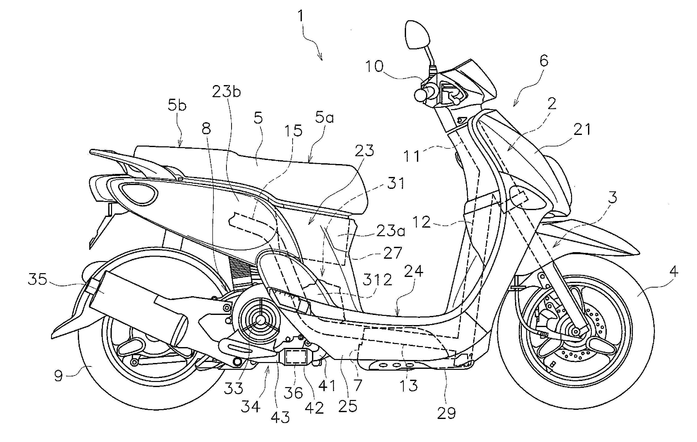
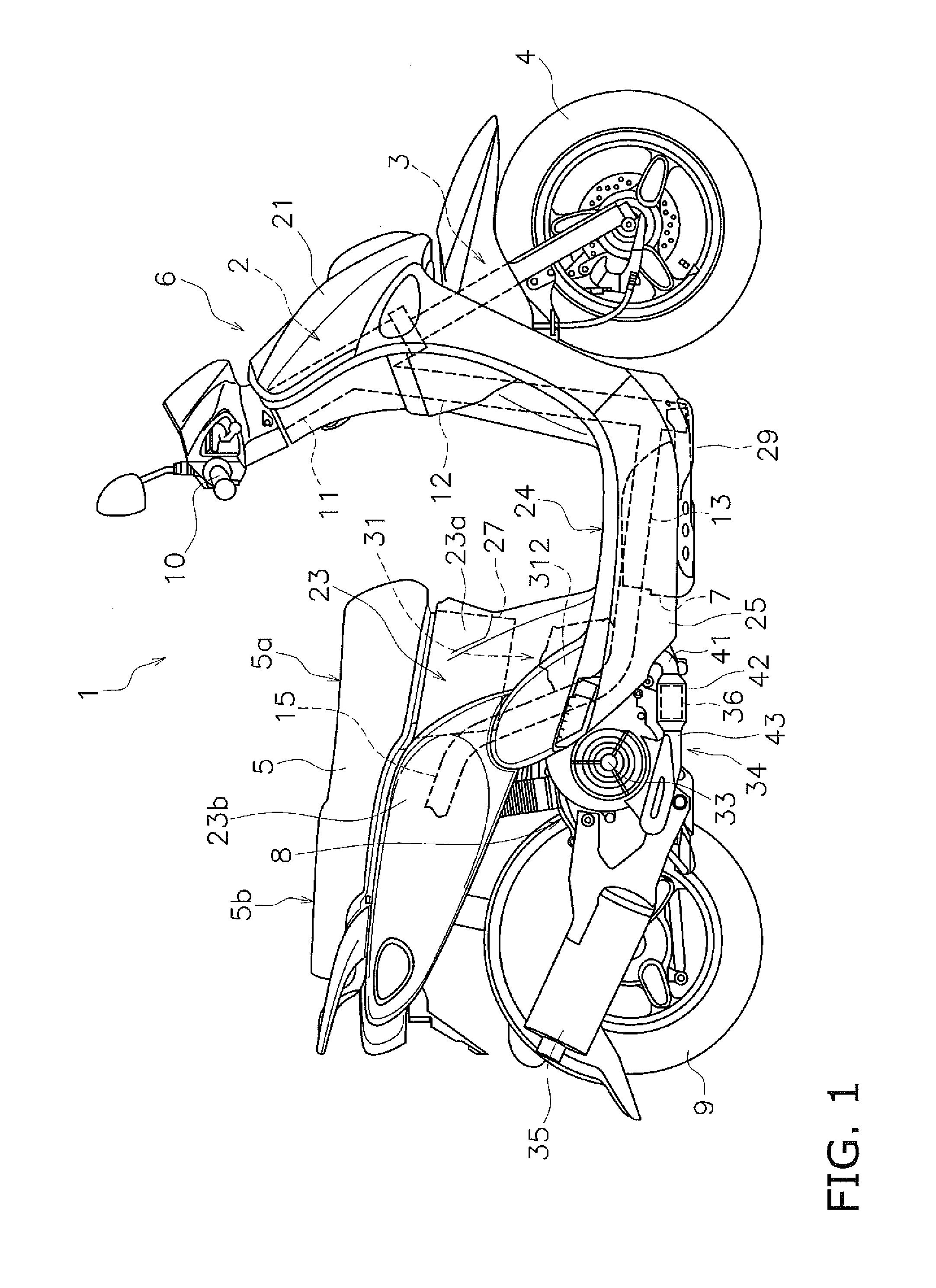
[0060]Saddle-riding vehicles according to exemplary preferred embodiments will be hereinafter explained with reference to the attached drawings. FIG. 1 is a right side view of a saddle-riding vehicle 1 according to the exemplary preferred embodiments. The saddle-riding vehicle 1 is preferably a scooter-type motorcycle, for example. The saddle-riding vehicle 1 includes a vehicle body frame 2, a front fork 3, a front wheel 4, a seat 5, a vehicle body cover 6, a fuel tank 7, an engine unit 8, and a rear wheel 9. It should be noted that in the exemplary preferred embodiments, directional terms “front”, “rear”, “right” and “left” and their related terms refer to those as seen from a rider seated on the seat 5.

[0061]The vehicle body frame 2 includes a head pipe 11 and a down frame 12. The front fork 3 is turnably supported by the head pipe 11. A handle 10 is attached to the upper portion of the front fork 3. The front wheel 4 is rotatably supported by the lower portion of the front fork 3...


PUM


Abstract

A fuel tank is disposed under a flat footboard. A vehicle body cover is disposed laterally of the fuel tank. An opening introduces travelling wind to a space between the fuel tank and the vehicle body cover. A first exhaust pipe is located upstream of a catalyst and is connected to an exhaust port. A catalyst housing portion accommodates the catalyst, is connected to the first exhaust pipe, and extends backwardly from the first exhaust pipe. A second exhaust pipe is located downstream of the catalyst, is connected to the catalyst housing portion, extends backwardly from the catalyst housing portion, and is connected to a silencer. The first exhaust pipe at least partially overlaps with the fuel tank in a vehicle front view. The catalyst housing portion is at least partially disposed rearward of the space between the fuel tank and the vehicle body cover.

Description

BACKGROUND OF THE INVENTION[0001]1. Field of the Invention[0002]The present invention relates to a saddle-riding vehicle.[0003]2. Description of the Related Art[0004]Some motorcycles have a structure in which a fuel tank is disposed under a flat footboard due to reasons such as increasing the capacity of a storage box (see, e.g., Japan Laid-open Patent Application Publication No. JP-A-2007-8316).[0005]On the other hand, saddle-riding vehicles have been demanded to dispose a catalyst to process exhaust gas as upstream as possible within an exhaust pipe in order to quickly activate the catalyst. For example, Japan Laid-open Patent Application Publication No. JP-A-2013-36422 discloses a motorcycle including a catalyst disposed upstream of a silencer.[0006]Further, the motorcycles described in JP-A-2007-8316 and JP-A-2013-36422, respectively include an engine unit composed of an engine, an exhaust pipe connected to the engine, and a silencer connected to the exhaust pipe. The engine uni...

Claims


Application Information

Patent Timeline
Patent Type & Authority Applications(United States)
IPC IPC(8): B62K11/04F01N13/00B60K13/04F01N3/28B62J25/00B62J35/00F02M37/00F02B61/02
CPCB62K11/04F02M37/007F01N13/002B60K13/04F01N3/28B62J25/00B62J35/00F02B61/02B62K2202/00B62J17/10B62J25/04F01N3/10F01N2340/04F01N2590/04Y02A50/20
Inventor INOMORI, TOSHINORIINOUE, RYUJI
Owner YAMAHA MOTOR CO LTD
Why Eureka
Try Eureka