Variable valve timing camshaft

a timing cam and variable valve technology, applied in valve arrangements, machines/engines, mechanical equipment, etc., can solve problems such as interference with surrounding devices, deterioration of reactivity or durability, etc., and achieve the effect of simple composition and connection structure and improved operating performan

Active Publication Date: 2015-06-18
HYUNDAI MOTOR CO LTD
View PDF1 Cites 8 Cited by
  • Summary
  • Abstract
  • Description
  • Claims
  • Application Information

AI Technical Summary

Benefits of technology

[0012]Various aspects of the present invention are directed to providing a variable valve timing camshaft having advantages of having a simpl

Problems solved by technology

However, reactivity or durability may be deteriorated if a connection structure with or composition of the CVVT apparatus for contr

Method used


Image

  • Variable valve timing camshaft
  • Variable valve timing camshaft
  • Variable valve timing camshaft

Examples


Embodiment Construction

[0029]Reference will now be made in detail to various embodiments of the present invention(s), examples of which are illustrated in the accompanying drawings and described below. While the invention(s) will be described in conjunction with exemplary embodiments, it will be understood that the present description is not intended to limit the invention(s) to those exemplary embodiments. On the contrary, the invention(s) is / are intended to cover not only the exemplary embodiments, but also various alternatives, modifications, equivalents and other embodiments, which may be included within the spirit and scope of the invention as defined by the appended claims.

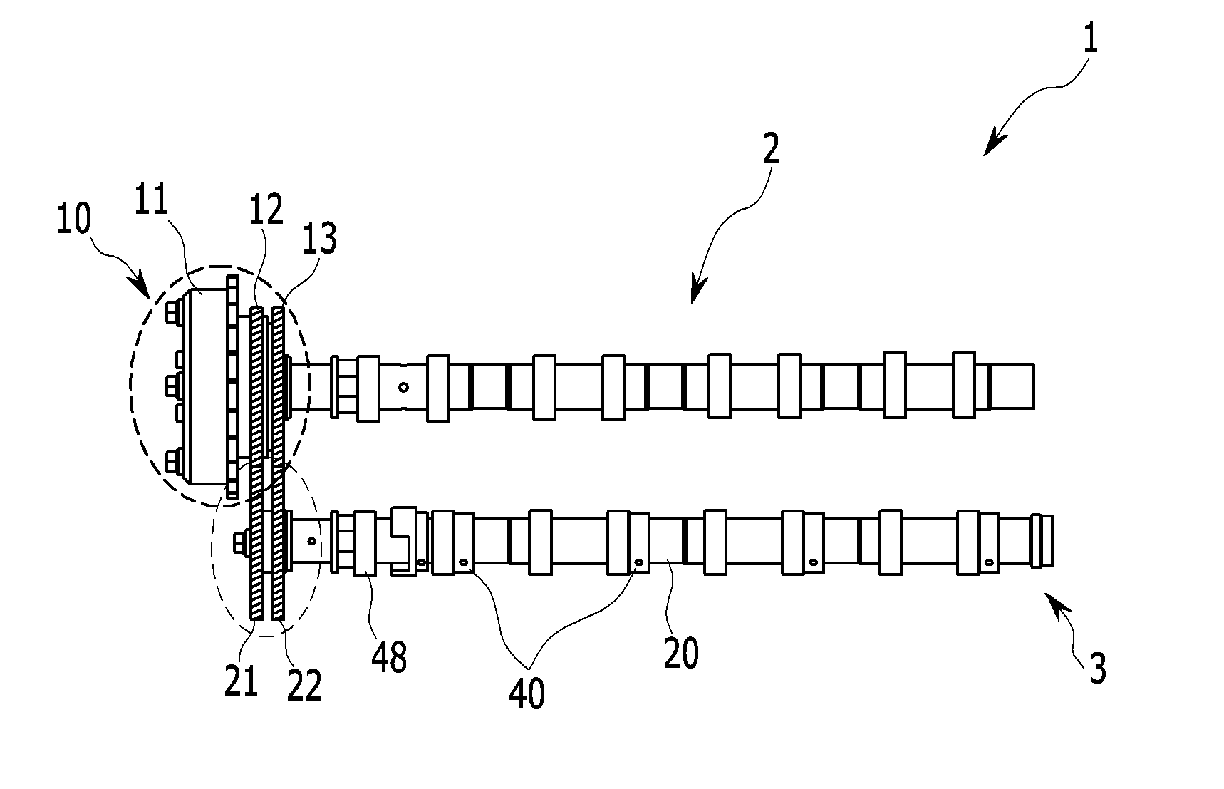
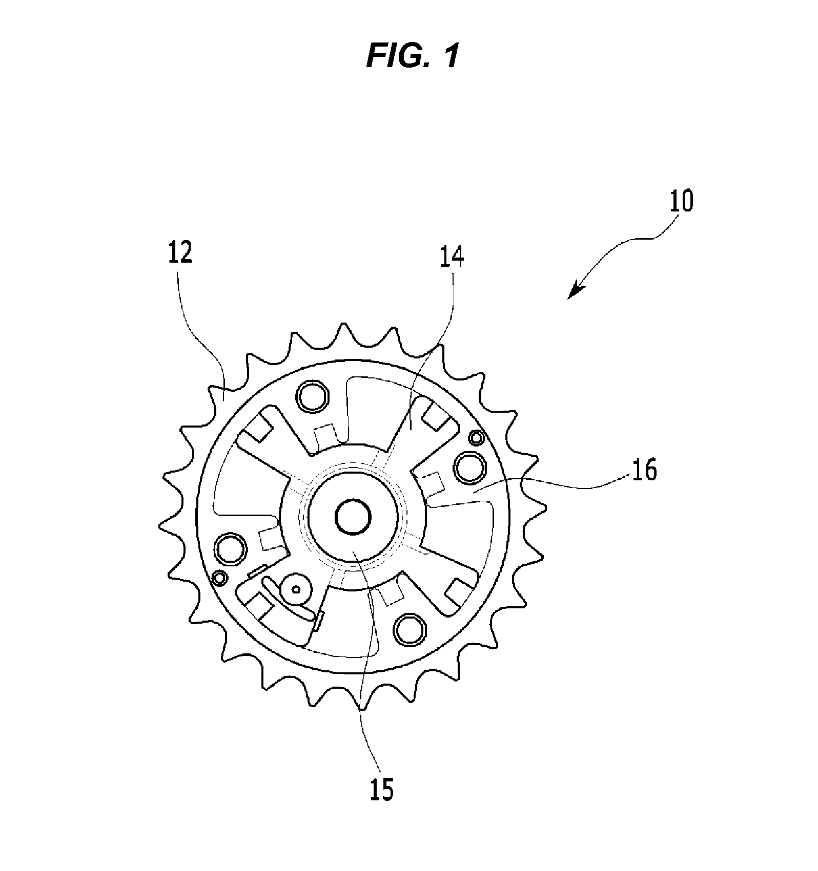
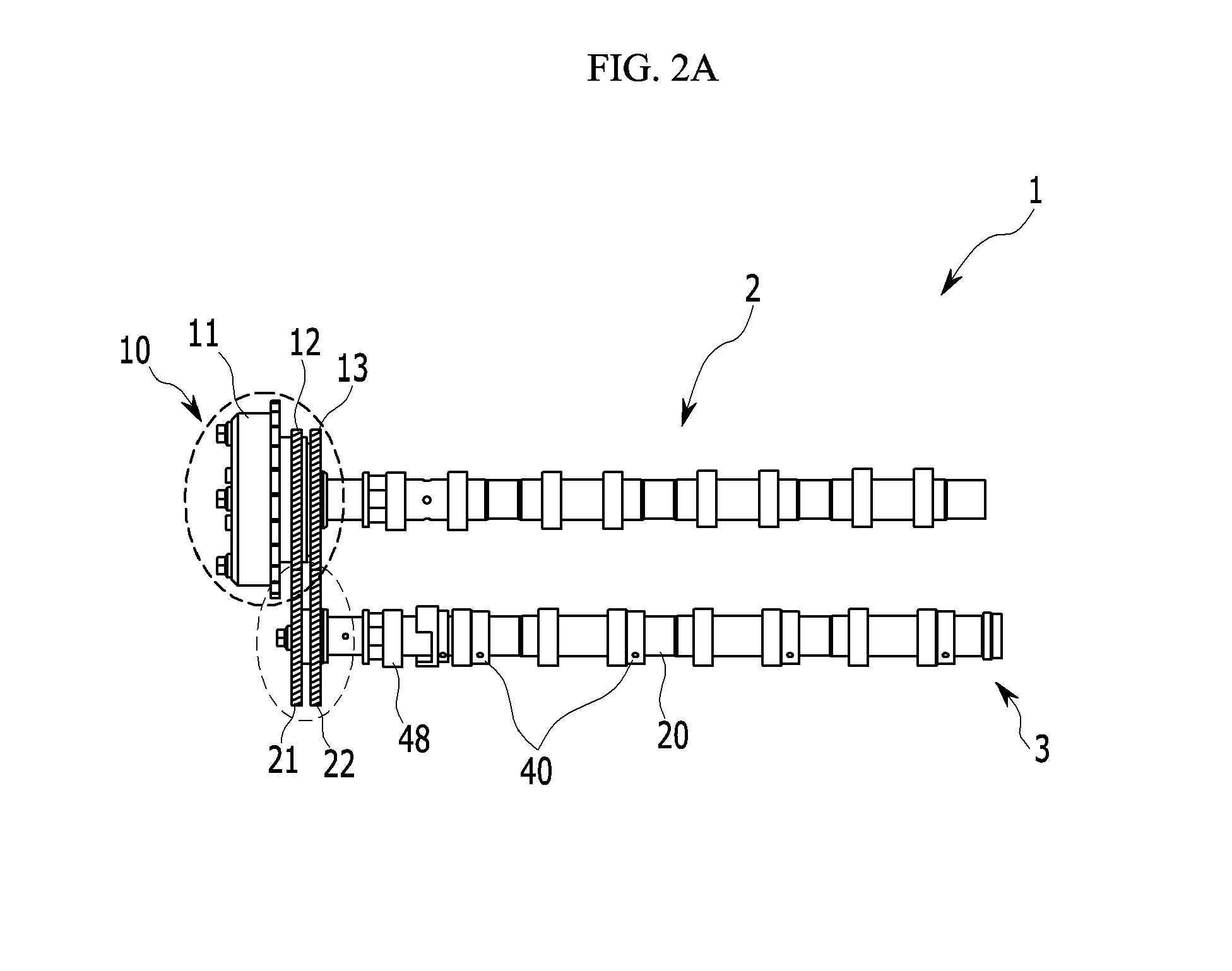
[0030]FIG. 1 is a schematic diagram of a basic continuous variable valve timing apparatus which is connected with a variable valve timing camshaft according to various embodiments of the present invention.

[0031]As shown in FIG. 1, the continuous variable valve timing (CVVT) apparatus 10 basically includes a rotor 15, a stator 16, ...


PUM


Abstract

A variable valve timing camshaft which may be connected to a continuous variable valve timing apparatus having a rotor and a stator which are adapted to relatively rotate with each other and may be operated so as to vary open/close timing of valve may include a non-control camshaft coupled to the continuous variable valve timing apparatus, having a first drive gear rotating together with the rotor and a second drive gear rotating together with the stator, and rotating according to rotation of an engine without varying a phase along a circumferential direction, a control camshaft having an outer shaft rotating according to one of the first drive gear or the second drive gear, an inner shaft rotating according to the other of the first drive gear or the second drive gear, an outer cam, and an inner cam and a limiting device limiting end play of the inner shaft.

Description

CROSS-REFERENCE TO RELATED APPLICATION[0001]The present application claims priority to Korean Patent Application No. 10-2013-0157594 filed Dec. 17, 2013, the entire contents of which is incorporated herein for all purposes by this reference.BACKGROUND OF THE INVENTION 1. Field of the Invention[0002]The present invention relates to a variable valve timing camshaft. More particularly, the present invention relates to a variable valve timing camshaft which is adapted to vary open / close timing of a valve.[0003]2. Description of Related Art[0004]Generally, an intake valve which is selectively opened or closed so as to supply fuel for combustion and an exhaust valve which is selectively opened or closed so as to exhaust exhaust gas formed by the combusted fuel are provided in a combustion chamber of an engine.[0005]The determining of open / close timing of the valve (intake valve or exhaust valve) may depend on a shape of a cam, rotation speed of a camshaft, and so on.[0006]In detail, the c...

Claims


Application Information

Patent Timeline
IPC IPC(8): F01L1/344
CPCF01L2001/34456F01L1/3442F01L1/026F01L2001/0473F01L2001/0537F01L1/047F01L1/34
Inventor KIM, HYOUNGHYOUN
Owner HYUNDAI MOTOR CO LTD
Why Eureka
Try Eureka