
Transmission

Active Publication Date: 2015-06-18
ZF FRIEDRICHSHAFEN AG
View PDF2 Cites 5 Cited by
  • Summary
  • Abstract
  • Description
  • Claims
  • Application Information

AI Technical Summary

Benefits of technology

The present invention proposes a transmission that has small gear intervals within a large transmission range. This transmission is optimized in relation to the space required for fitting and has high efficiency.

Problems solved by technology

With such a structure, however, the electric drive must cover the complete rotational speed range and this reduces its overall efficiency.
Furthermore, the rotational speed range that can be realized is rather narrow.
However, precisely because the transmission is made with sliding sleeves, there is a traction force interruption during the shift.
For automated drive-trains, however, such a traction force interruption results in a considerable impairment of comfort, which is undesired by the customer or the driver.

Method used


Image

  • Transmission
  • Transmission
  • Transmission

Examples


Embodiment Construction

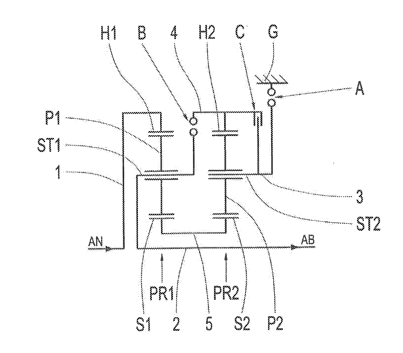
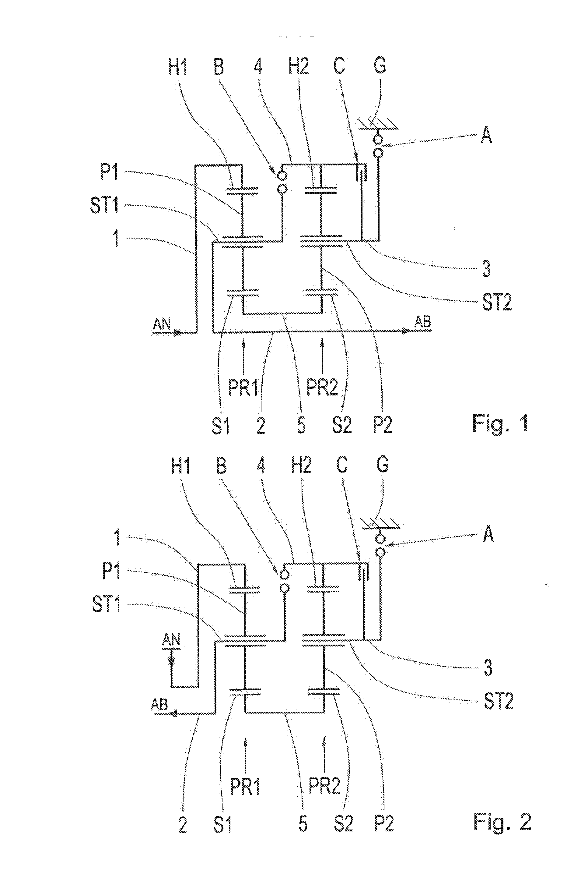
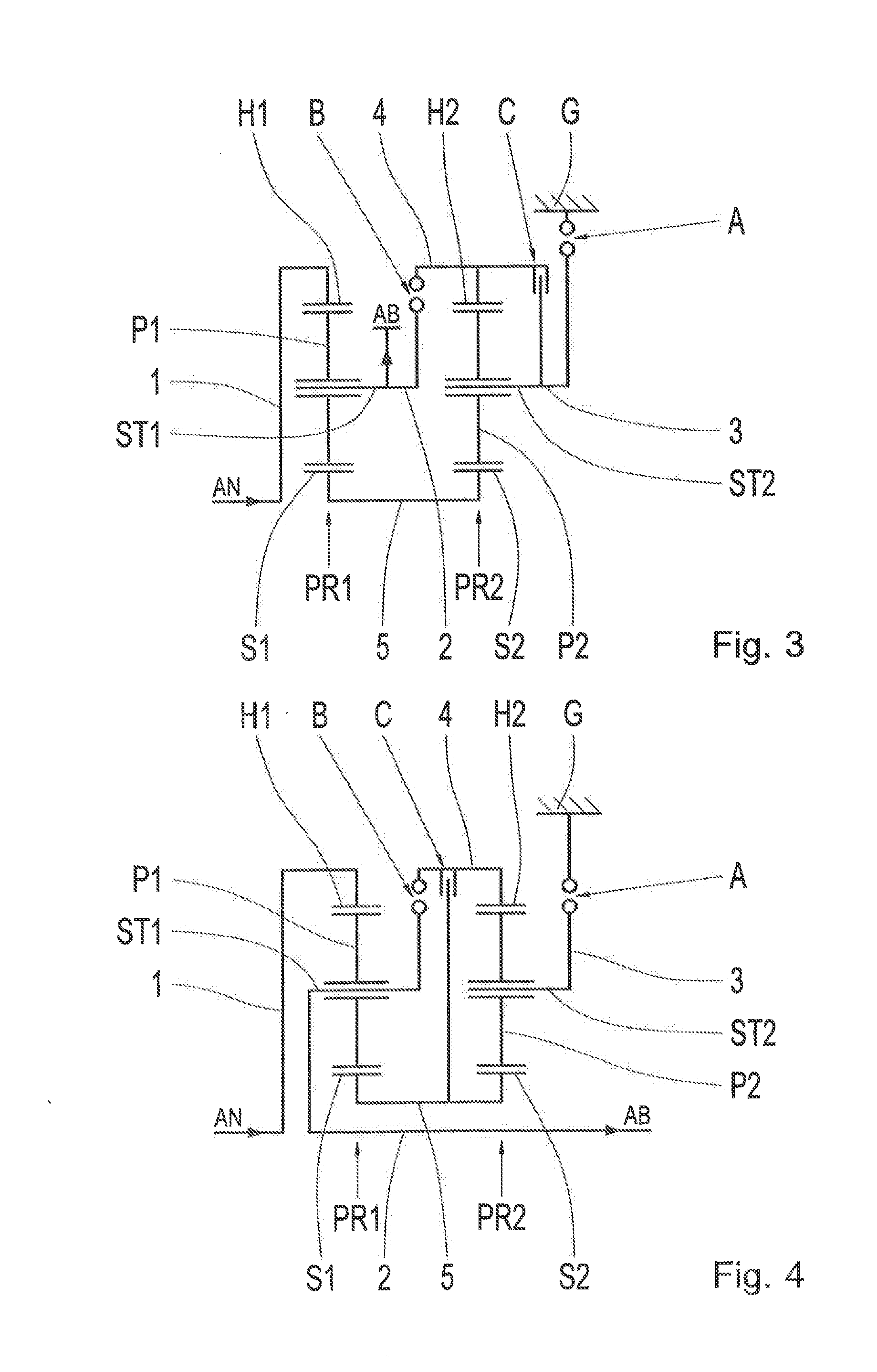
[0082]FIG. 1 shows a schematic representation of a first embodiment of the transmission according to the invention, according to the first configuration of the invention. The transmission comprises a drive input shaft AN, a drive output shaft AB, a first planetary gearset PR1, a second planetary gearset PR2 and three shifting elements A, B, C, all of them accommodated in a housing G. In this example embodiment the two planetary gearsets PR1, PR2 are designed as simple minus planetary gearsets. The ring gears of the two planetary gearsets PR1, PR2 are indexed H1 and H2, their sun gears S1 and S2, their planetary gearwheels P1 and P2 and the carriers on which the planetary gearwheels P1, P2 are mounted to rotate are indexed ST1 and ST2. The transmission has five rotary shafts, indexed 1 to 5.

[0083]With regard to the coupling of the individual elements of the two planetary gearsets PR1, PR2 with one another and to the drive input shaft AN and the drive output shaft AB, in the transmiss...


PUM


Abstract

A transmission having a drive input shaft (AN), a drive output shaft (AB), a housing (G), at least two planetary gearsets (PR1, PR2), and at least three shifting elements (A, B, C) whose selective engagement produces various transmission ratios between the drive input shaft (AN) and the drive output shaft (AB), so that at least three gears can be obtained. To obtain a gear in each case, two shifting elements are engaged and a further shifting element is disengaged.

Description

[0001]This application claims priority from German patent application serial no. 10 2013 226 479.8 filed Dec. 18, 2013.FIELD OF THE INVENTION[0002]The present invention concerns a transmission, in particular a three-gear transmission for a motor vehicle, preferably for use in a drive-train of electric vehicles or in a drive-train of hybrid vehicles. The present invention also concerns a method of operating such a transmission and a drive-train with such a transmission.BACKGROUND OF THE INVENTION[0003]Here, ‘transmission’ denotes a multi-gear transmission in which a predefined number of gears, i.e. fixed transmission ratios between the transmission input and the transmission output, can be engaged automatically by means of shifting elements. The shifting elements are for example clutches and / or brakes.[0004]At present, as drive systems for electric vehicles one-gear transmissions are mainly used, i.e. simple step-down stages with an output rotational speed lower compared with the inp...

Claims


Application Information

Patent Timeline
IPC IPC(8): F16H3/44
CPCF16H3/44F16H2200/0091F16H2200/0039F16H3/66F16H3/666F16H2200/2094F16H2200/2064F16H2200/201F16H2200/2007F16H2200/2038
Inventor BECK, STEFANKALTENBACH, JOHANNESKEHR, ULRICHTRUBENBACH, MICHAEL
Owner ZF FRIEDRICHSHAFEN AG
Learn More