Diaphragm and Diaphragm Valve

a diaphragm valve and diaphragm technology, which is applied in the direction of diaphragm valves, engine diaphragms, valve housings, etc., can solve the problems of substantial reduction of sealing properties, increase of manufacturing costs, and poor flexibility of ptfe membranes, so as to reduce the reduction of sealing properties and prevent cart deformation. , the effect of excellent durability

a diaphragm valve and diaphragm technology, which is applied in the direction of diaphragm valves, engine diaphragms, valve housings, etc., can solve the problems of substantial reduction of sealing properties, increase of manufacturing costs, and poor flexibility of ptfe membranes, so as to reduce the reduction of sealing properties and prevent cart deformation. , the effect of excellent durability

US20150167853A1Active Publication Date: 2015-06-18FUJIKIN INC

Image

  • Diaphragm and Diaphragm Valve
  • Diaphragm and Diaphragm Valve
  • Diaphragm and Diaphragm Valve

Examples


Embodiment Construction

[0037]Hereinafter, suitable embodiments of the diaphragm and the diaphragm valve according to the present invention will be explained with reference to the drawings.

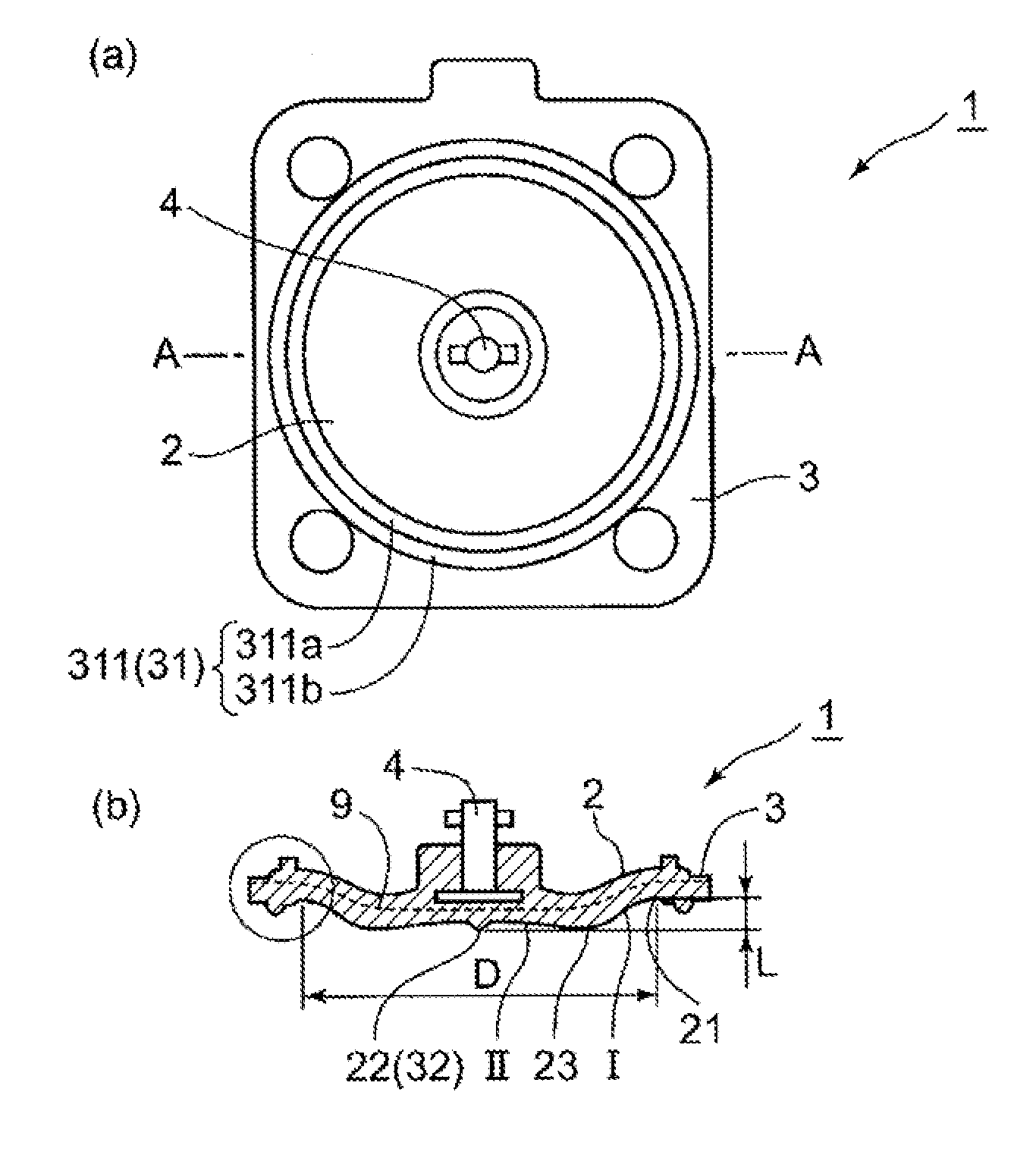
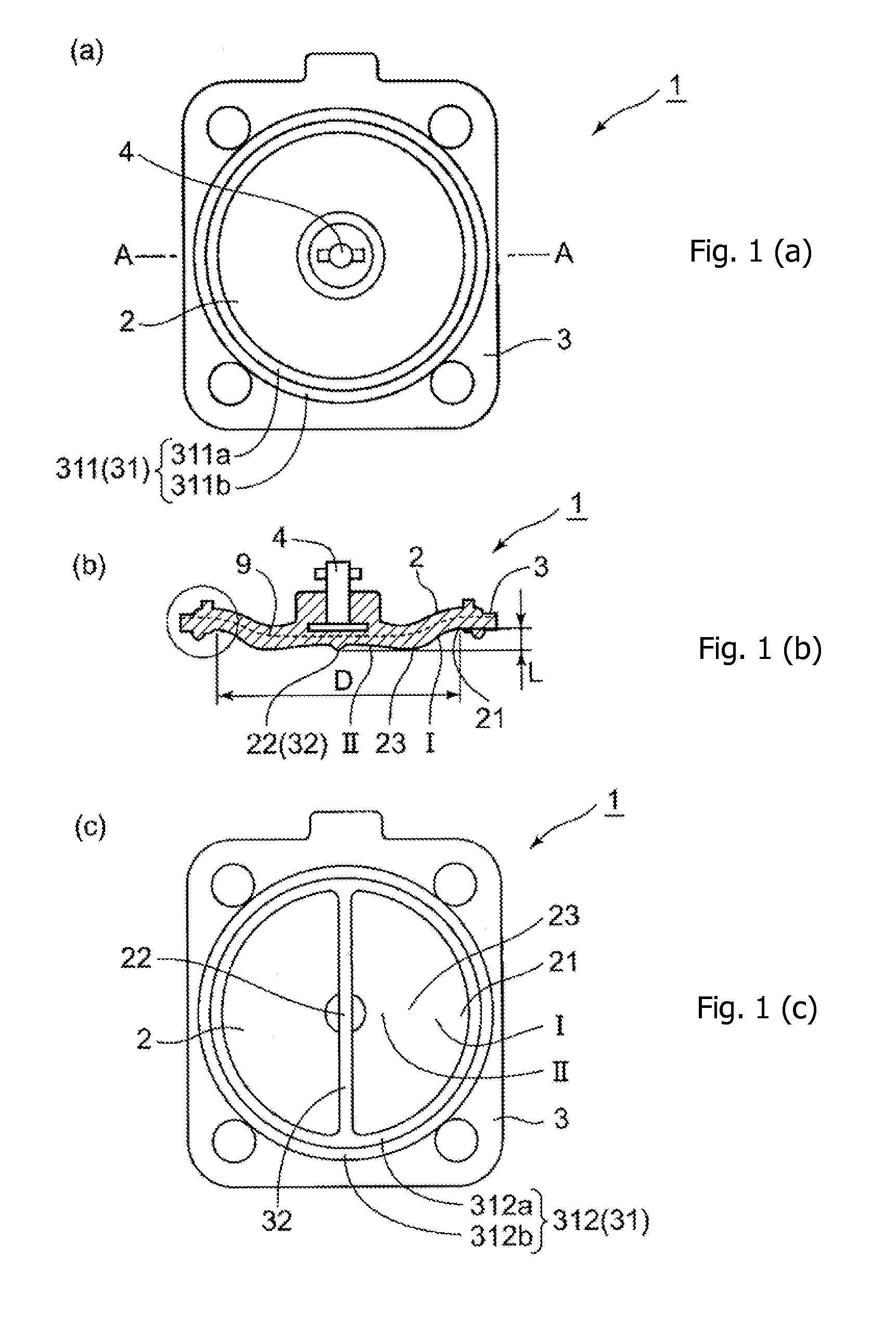
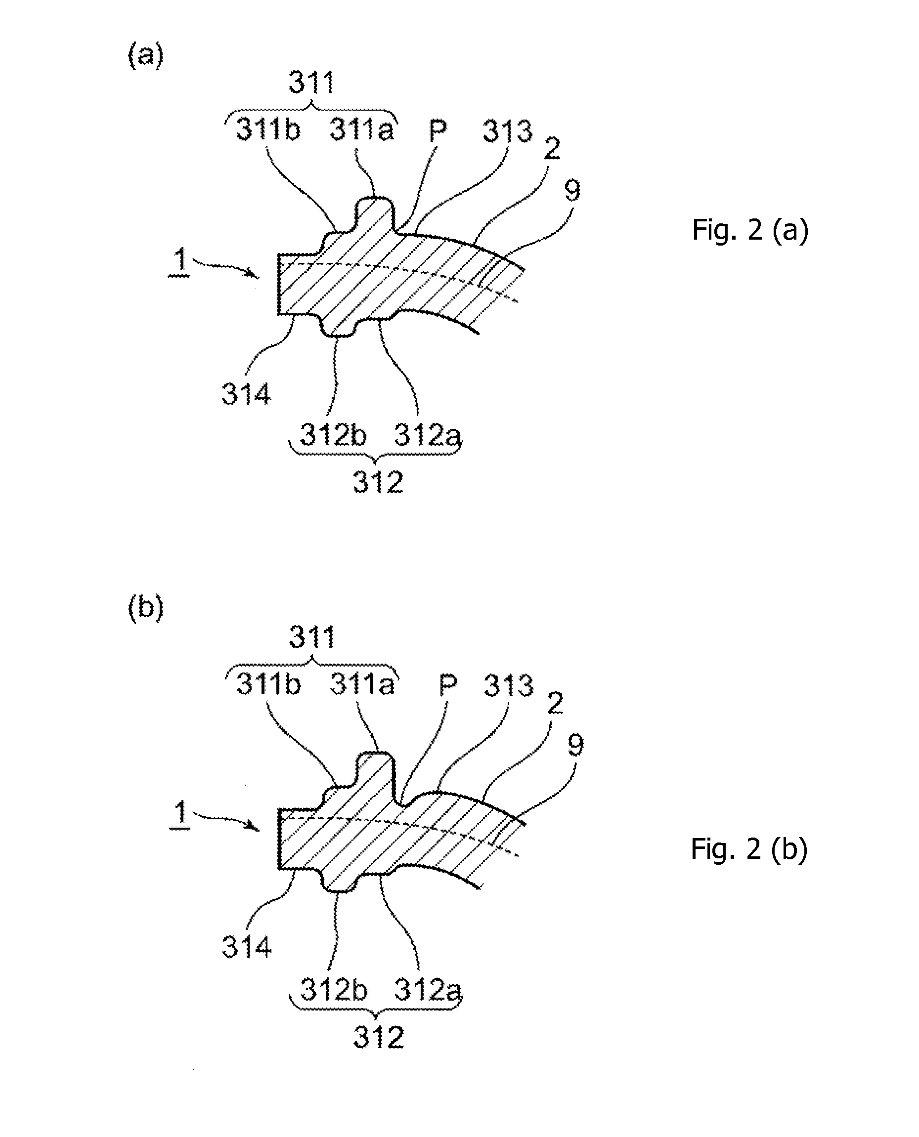
[0038]FIG. 1 shows views illustrating a diaphragm according to the present invention. FIG. 1 (a) is a top view. FIG. 1 (b) is to sectional view taken along the line A-A of FIG. 1 (a), and FIG. 1 (c) is a bottom view FIG. 2 (a) is an enlarged view in the circle of FIG. 1(b) and FIG. 2 (b) shows the change example.

[0039]A diaphragm (1) according to the present invention comprises as membrane part (2) deforming and moving up and down with opening and closing of a flow channel of a diaphragm valve and a flange part (3) which is provided around this membrane part (2) and sandwiched between a valve body and a bonnet of a diaphragm valve.

[0040]The diaphragm (1) according to the present invention is a diaphragm of a single-layer structure consisting of rubber materials. As a rubber material, a natural rubber, a nitrile rubber, a...


PUM


Abstract

A durable diaphragm valve has a single-layer structure consisting of rubber materials. The single-layer structure has a membrane part deforming and moving up and down with opening and closing of a flow channel and a flange part which is provided around said membrane part and sandwiched between a valve body and a bonnet. The flange part has an annular ridge consisting of an upper ridge protruding upward and a lower ridge protruding downward from a position corresponding to said upper ridge. The upper ridge has an inner upper ridge and an outer upper ridge with its protruding height being lower than the inner upper ridge, which are consecutively formed in a staircase pattern.

Description

TECHNICAL FIELD[0001]The present invention relates to a diaphragm and a diaphragm valve, more particularly a diaphragm with high durability which can restrain reduction of sealing properties and occurrence of a crack resulting from repeated opening and closing of a flow channel of the diaphragm valve, and a diaphragm valve.BACKGROUND OF THE INVENTION[0002]Conventionally, a two-layer structure with a synthetic resin membrane consisting of FIFE, etc. and a rubber membrane consisting of EPDM, FPM, etc. is known as a diaphragm attached to a diaphragm valve. (For example, see Patent Document 1 below)[0003]FIG. 8 is a longitudinal sectional view showing an example of a diaphragm having a two-layer structure.[0004]This diaphragm has a two-layer structure in which a rubber membrane (B) consisting of EPDM, FPM, etc. is laminated on a synthetic resin membrane (A) consisting of PTFE, etc.[0005]An annular ridge, which functions as a guide when attached to the diaphragm valve, is provided in a v...

Claims


Application Information

Patent Timeline
18 Jun 2015
Publication
US20150167853A1
IPC
F16K7/12
CPC
F16K7/12; F16J3/02; F16K7/126; F16K31/1221; F16K27/0236; F16K31/02; F04B43/0054
Inventors
OBARA, SHUNJI; SHIMOMURA, YOSHINORI