
Information processing apparatus and control method of information processing apparatus

a technology of information processing apparatus and control method, which is applied in the direction of instruments, static indicating devices, optical elements, etc., can solve the problems of difficult to mount a sensor other than the gyro sensor embedded in the operation unit, difficult to perform a plurality of control operations corresponding, and difficult to perform the plurality of control operations without changing the os

Active Publication Date: 2015-06-18
SEIKO EPSON CORP
View PDF12 Cites 7 Cited by
  • Summary
  • Abstract
  • Description
  • Claims
  • Application Information

AI Technical Summary

Benefits of technology

The patent describes an information processing apparatus that improves user operability by detecting the direction of operation using the acceleration of the operation unit. This allows users to input using the detected acceleration as a reference, rather than the direction of the operation unit. Additionally, the control processing unit includes an operating system and the input and output conversion unit is a device driver or middleware, reducing the load on the control operation and the development period of the information processing apparatus.

Problems solved by technology

However, in the head mounted display disclosed in JP-A-2011-82781, the operation of the head mounted display may be performed with the gyro sensor embedded in the operation unit, but it is difficult to mount a sensor other than the gyro sensor embedded in the operation unit in order to perform an operation different from the operation performed with the angular velocity detected by the gyro sensor, according to a detected result of the other sensor.
In addition, depending on an operation system (hereinafter, also simply referred to as an “OS”), it is difficult to perform a plurality of control operations corresponding to each detected result, with respect to the detected results from the plurality of sensors, and it is difficult to perform the plurality of control operations without changing the OS.
The problems described above are not limited to the head mounted display, but commonly occur in an information processing apparatus including an operation unit.

Method used


Image

  • Information processing apparatus and control method of information processing apparatus
  • Information processing apparatus and control method of information processing apparatus
  • Information processing apparatus and control method of information processing apparatus

Examples


embodiment

A. Embodiment

A-1. Configuration of Head Mounted Display

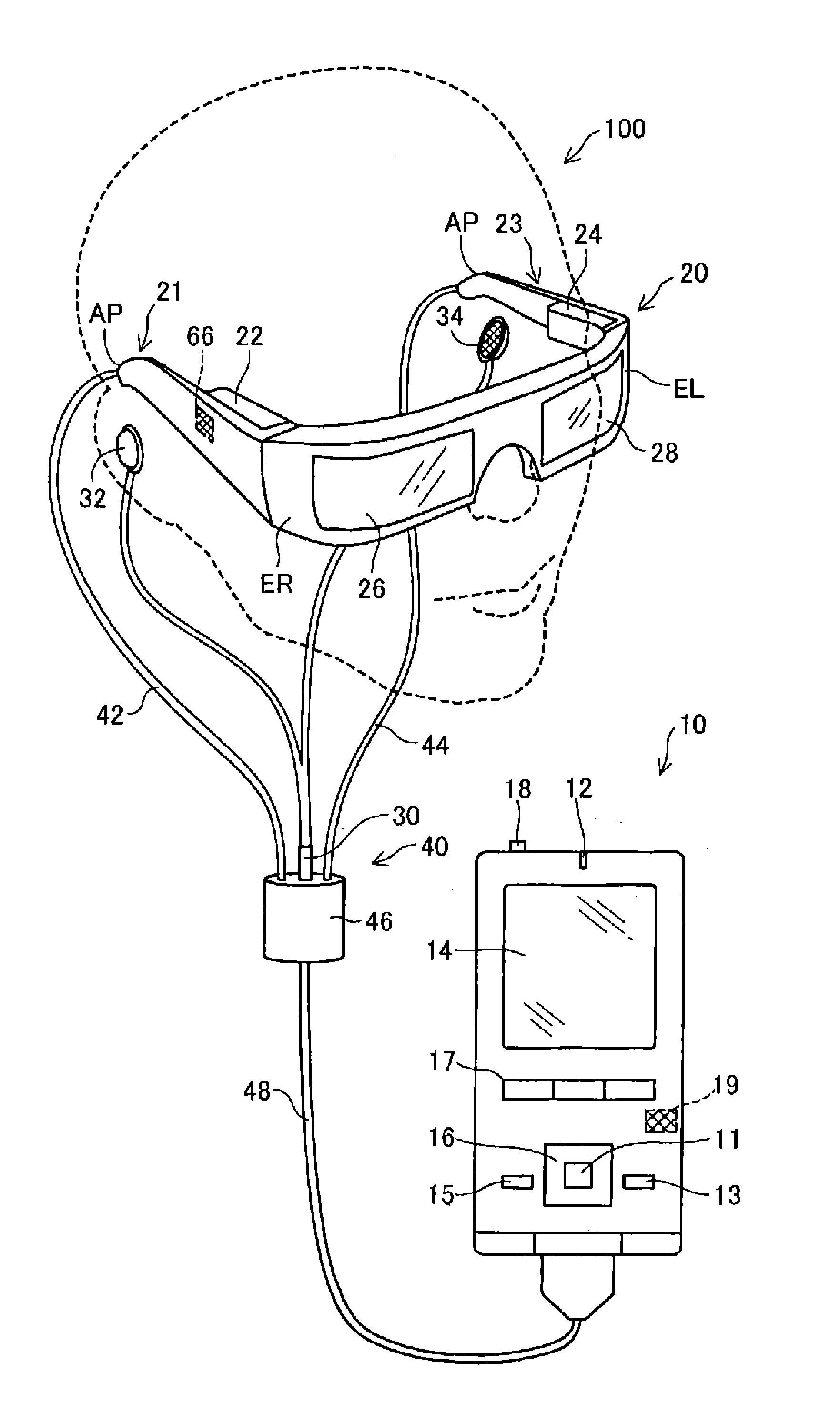
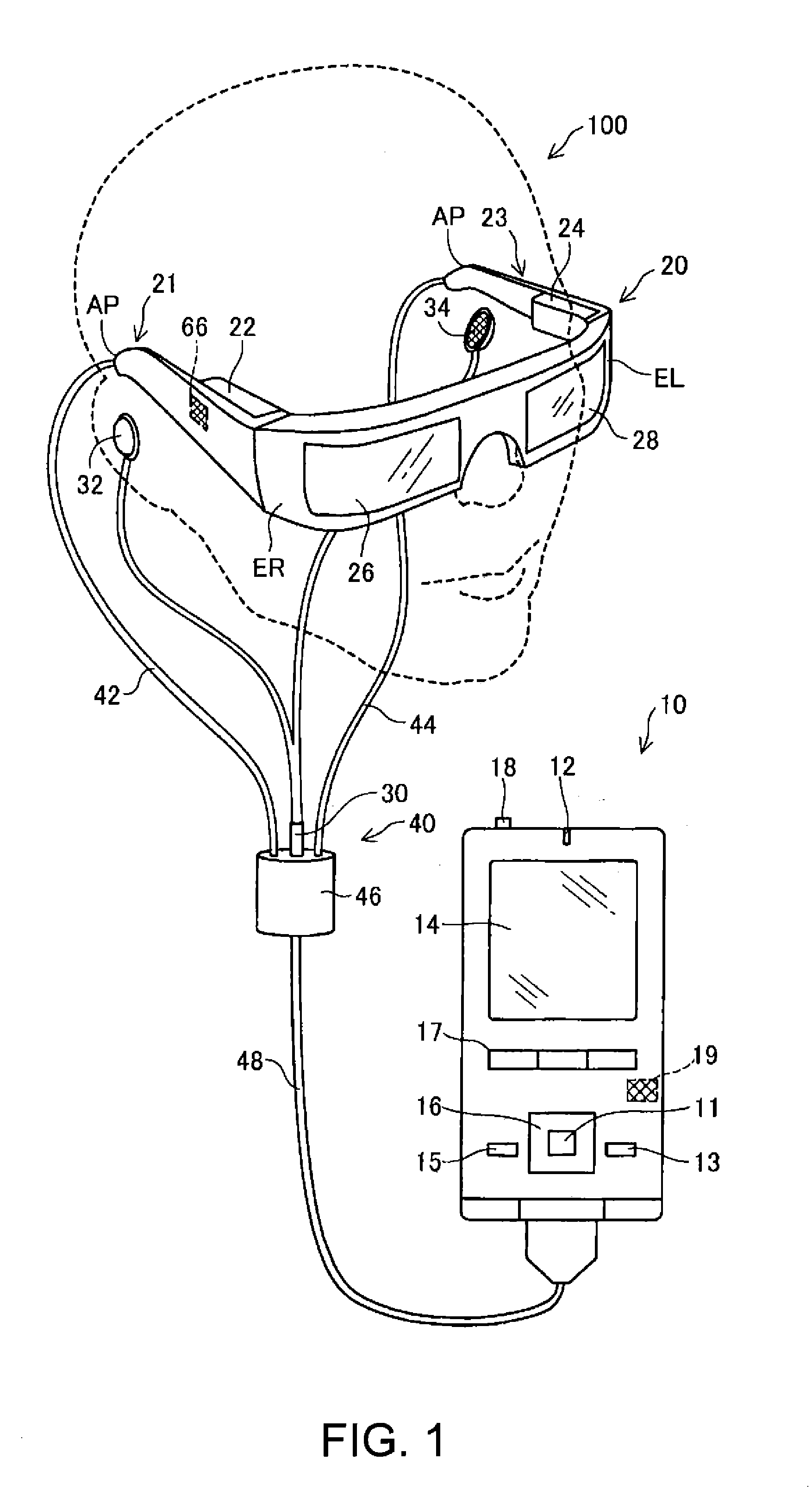
[0030]FIG. 1 is an explanatory diagram showing an appearance configuration of a head mounted display 100. The head mounted display 100 is a display device to be mounted on the head, and is also called a head mounted display (HMD). The head mounted display 100 of the embodiment is an optical transmission type head mounted display which allows a user to visually recognize a virtual image and to directly visually recognize external scenery at the same time. In the present specification, the virtual image which is visually recognized by a user using the head mounted display 100 is also referred to as a “display image” for the sake of convenience. In addition, emission of image light generated based on image data is also referred to as “display of an image”.

[0031]The head mounted display 100 includes an image display unit 20 which allows a user to visually recognize a virtual image in a state of being mounted on the head of a user, a...

modification example

B. Modification Example

[0071]The invention is not limited to the embodiment and can be executed in various embodiments within a range not departing from the gist thereof, and for example, the following modifications can also be performed.

modification example 1

B1. Modification Example 1

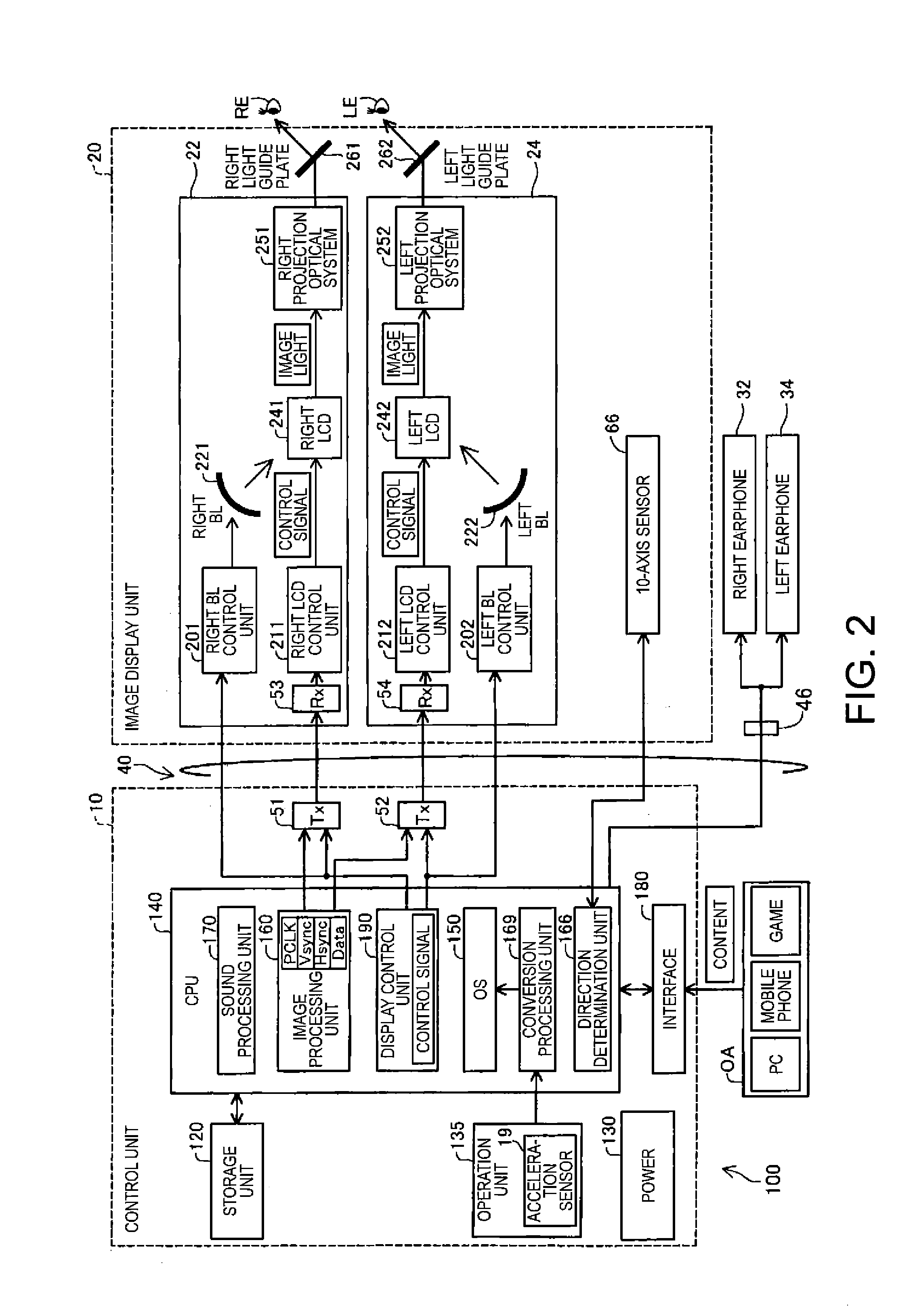
[0072]In the embodiment, the 10-axis sensor 66 embedded in the image display unit 20 detects the state of the image display unit 20, and the acceleration sensor 19 included in the control unit 10 acquires the acceleration acting on the control unit 10, however, various modifications can be performed regarding the embodiment of each sensor. For example, the change of the direction of the control unit 10 and the position of the image display unit 20 is detected by a camera installed on a portion different from the control unit 10 and the image display unit 20, and the display image VI of the image display unit 20 may be controlled based on the detected results.

[0073]A 10-axis sensor may be embedded in the control unit 10 separately from the acceleration sensor 19, instead of the 10-axis sensor 66 embedded in the image display unit 20. For example, the inputs to the track pad 14 may be converted and output by the acceleration sensor 19 and the input and output...


PUM


Abstract

An information processing apparatus includes: an operation unit which receives an operation; a first detection unit which detects a direction of the operation unit; an input and output conversion unit which converts an input of the operation received by the operation unit into an output based on a first regulation, when the direction of the operation unit is in a first state, and converts the input into an output based on a second regulation which is different from the first regulation, when the direction of the operation unit is in a second state; a second detection unit which detects an apparatus state which is at least one of a position and a direction of the information processing apparatus; and a control processing unit which performs a control process of the information processing apparatus, based on the output from the input and output conversion unit and the apparatus state.

Description

BACKGROUND[0001]1. Technical Field[0002]The present invention relates to an information processing apparatus.[0003]2. Related Art[0004]A head mounted display (HMD) which is a display device to be mounted on the head has been known as one information processing apparatus. The head mounted display, for example, generates image light showing an image using a liquid crystal display and a light source, and introduces the generated image light to the eyes of a user using a projection optical system or a light guide plate, to allow a user to visually recognize a virtual image. An operation with buttons or a track pad, movement of the head of a user detected by various sensors, and the like are known as means for controlling the head mounted display.[0005]JP-A-2011-82781 discloses a head mounted display in which a gyro sensor is embedded in a remote controller which is an operation unit, and the head mounted display is operated according to an angular velocity detected by the gyro sensor. I...

Claims


Application Information

Patent Timeline
Patent Type & Authority Applications(United States)
IPC IPC(8): G02B27/01G06F3/01
CPCG02B27/017G02B2027/0178G06F3/01G06F3/0346G02B27/0172G02B27/0176G02B2027/014G02B2027/0187G06F3/012G06F3/013G06F3/03547G06F3/0484G06F3/04883G06F2203/0381G06T19/006
Inventor KIMURA, FUSASHINISHIZAWA, KAZUO
Owner SEIKO EPSON CORP
Learn More