

Feed unit, feed system, and electronic device
Active Publication Date: 2015-06-18
SONY CORP
View PDF7 Cites 26 Cited by
- Summary
- Abstract
- Description
- Claims
- Application Information
AI Technical Summary
Benefits of technology
The invention affects the resonance frequencies in a wireless power transmission system, which can improve power transmission efficiency and reduce transmission efficiency variation caused by positional changes. By adjusting the difference between the main and auxiliary resonance frequencies, the system can achieve improved planarization of transmission efficiency distribution. This results in improved power transmission efficiency and stability.
Problems solved by technology
Therefore, there is such an issue that feeding efficiency (transmission efficiency) at the time of non-contact feeding is nonuniform by being dependent on the relative position between the primary-side device and the secondary-side device (for example, the placement of the secondary-side device).
Method used
View moreImage
Smart ImageViewing Examples

Examples
first embodiment (
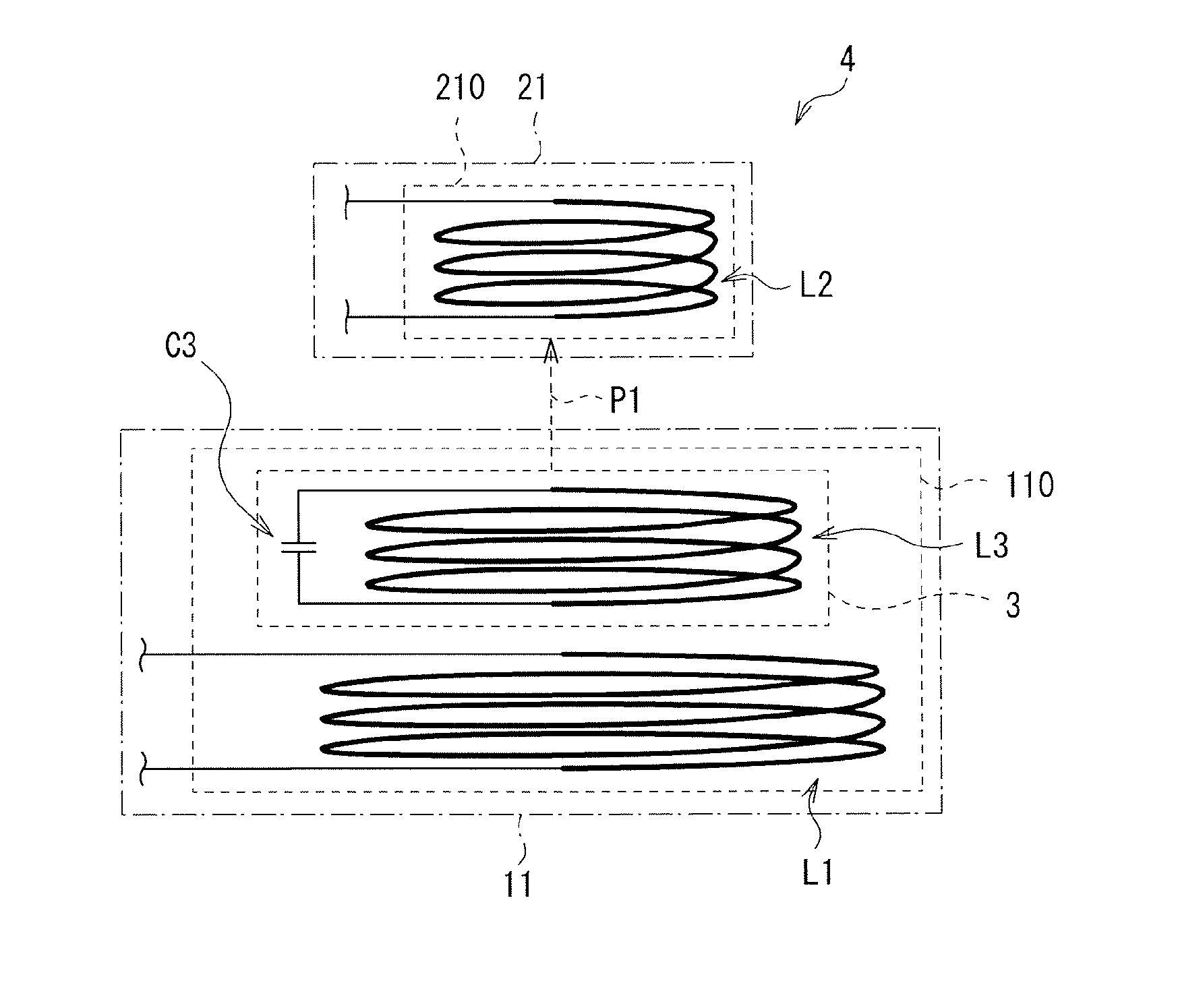
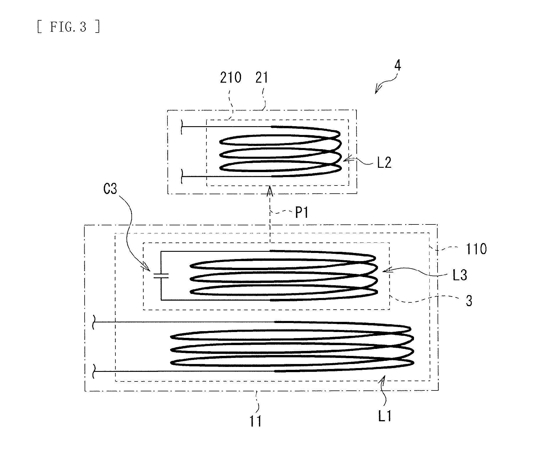
1. First embodiment (an example in which an auxiliary resonance section having a resonator is provided in a primary-side device)
second embodiment (
2. Second embodiment (another example in which an auxiliary resonance section having a resonator is provided in a primary-side device)
third embodiment (
3. Third embodiment (an example in which an auxiliary resonance section is provided in a secondary-side device)
Login to View More PUM
 Abstract
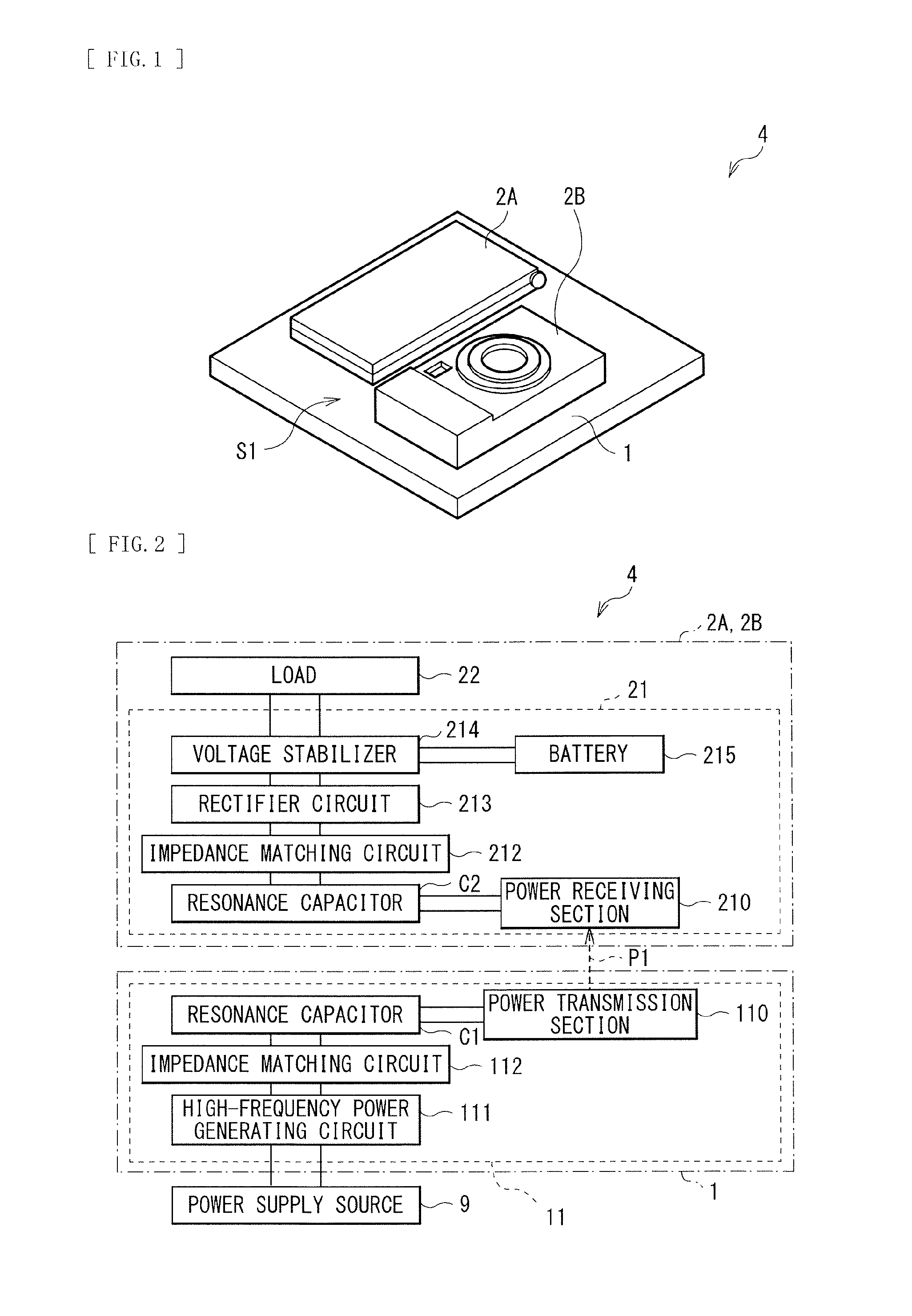
Provided are a feed unit, a feed system, and an electronic device that enable transmission efficiency control according to the position of a device when electric power transmission using a magnetic field is performed between devices. The feed unit includes a power transmission section including a power transmission coil configured to perform electric power transmission using a magnetic field, and an auxiliary resonance section including one or a plurality of resonators. The resonator includes an auxiliary coil wound to form a gap in at least a partial region.
Description
TECHNICAL FIELD[0001]The present disclosure relates to a feed system that performs non-contact electric power supply (electric power transmission) to an electronic device, as well as a feed unit and an electronic device applied to such a feed system.BACKGROUND ART[0002]In recent years, attention has been given to a feed system (a non-contact feed system and a wireless charging system) that performs non-contact electric power supply (electric power transmission) to a CE device (Consumer Electronics Device) such as a mobile phone and a portable music player, for example. This makes it possible to start charging merely by placing an electronic device (a secondary-side device) on a charging tray (a primary-side device), instead of starting charging by inserting (connecting) a connector of a power-supply unit such as an AC adapter into the device. In other words, terminal connection between the electronic device and the charging tray becomes unnecessary.[0003]As a method of thus performi...
Claims
Login to View More Application Information
Patent Timeline
 IPC IPC(8): H01F38/14H02J7/00
CPCH01F38/14H01F27/006H01M10/46H02J7/00045Y02E60/10H02J50/402H02J50/90H02J50/12H02J50/70H01F27/06
InventorMIYAMOTO, TAKASHI
OwnerSONY CORP