Synchronous Reluctance Motor and Underwater Pump

Inactive Publication Date: 2015-06-18
KSB AG
View PDF8 Cites 1 Cited by
  • Summary
  • Abstract
  • Description
  • Claims
  • Application Information

AI Technical Summary

Benefits of technology

The patent text describes a device that uses a medium to ensure constant lubrication of bearings and protect against corrosion. The device also includes flow barriers that can be sealed off to prevent the ingress of liquid. These flow barriers can be filled with plastic or other materials to prevent liquid ingress. The technical effect of this invention is to provide improved performance and durability of hydrodynamic bearings in various applications.

Problems solved by technology

As compared with air-filled motor spaces, however, the achievable efficiency and power factor of machines of this type are markedly reduced, since, inter alia because of the liquid medium in the motor space, the friction effect between the rotor and medium increases tremendously.
Just borehole depths of a few hundred meters incur enormous costs which are forestalled, for example, via restriction in the permissible borehole diameter.
However, limiting the maximum diameter places stringent requirements upon the development of the motor assemblies, since the physical dimensioning of the assembly, as a rule, critically codetermines its efficiency and power factor.
However, because the motor design in underwater motors is governed by their use, the use of synchronous reluctance motors in the underwater pump sector can be implemented at the present time only with considerable losses in terms of efficiency and of power factor.
However, using the ferrofluid entails an adverse concomitant phenomenon, since the increased permeability in the motor space also intensifies the leakage losses which occur.
A similar problem arises in the region of the slots of the stator body.
Here, too, because of the ferrofluid, the flux lines can be propagated more easily and cause higher losses.
In this case, there is the risk that the ferrofluid infiltrates into the cavity of the flow barriers.

Method used


Image

  • Synchronous Reluctance Motor and Underwater Pump
  • Synchronous Reluctance Motor and Underwater Pump

Examples


Embodiment Construction

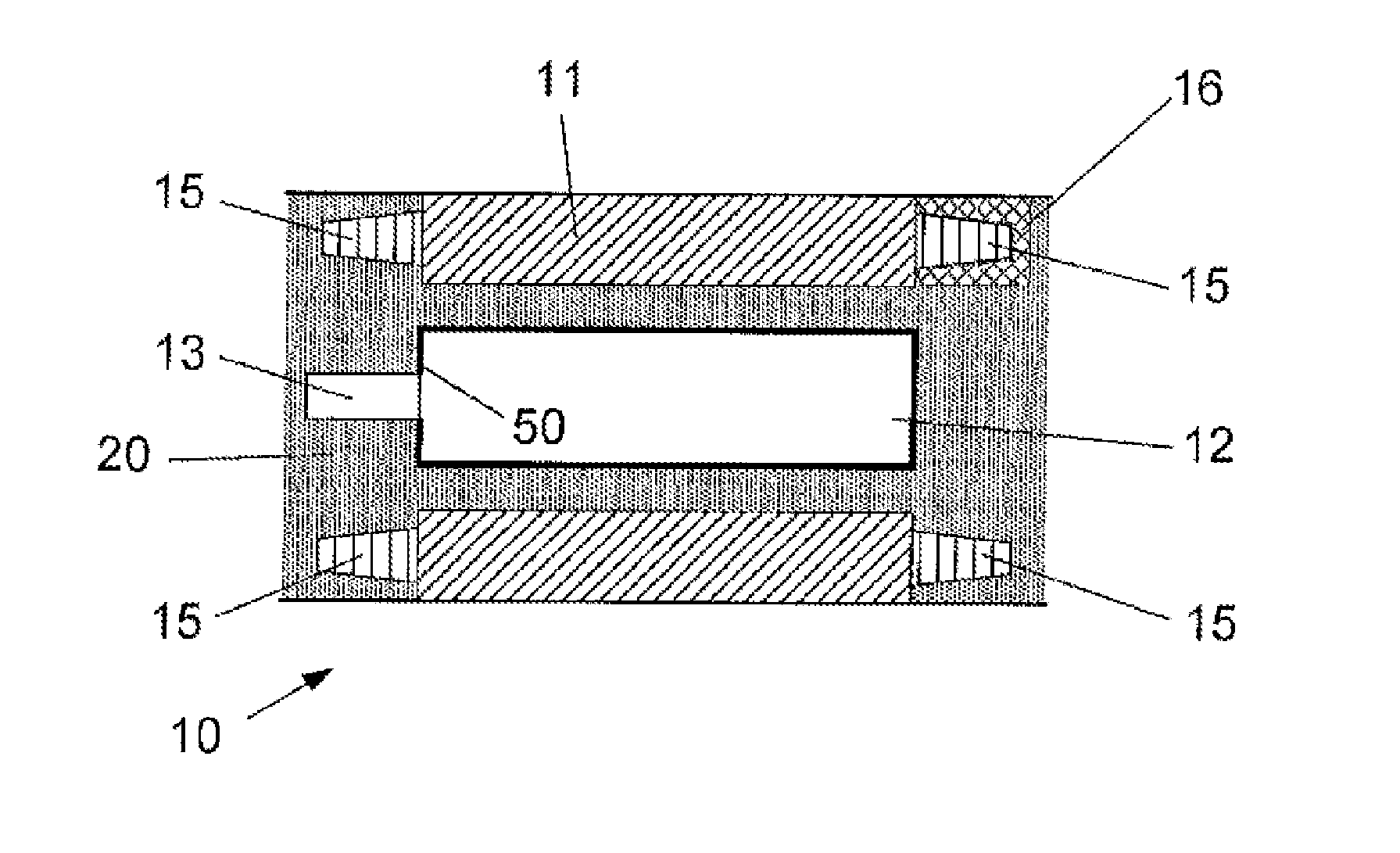
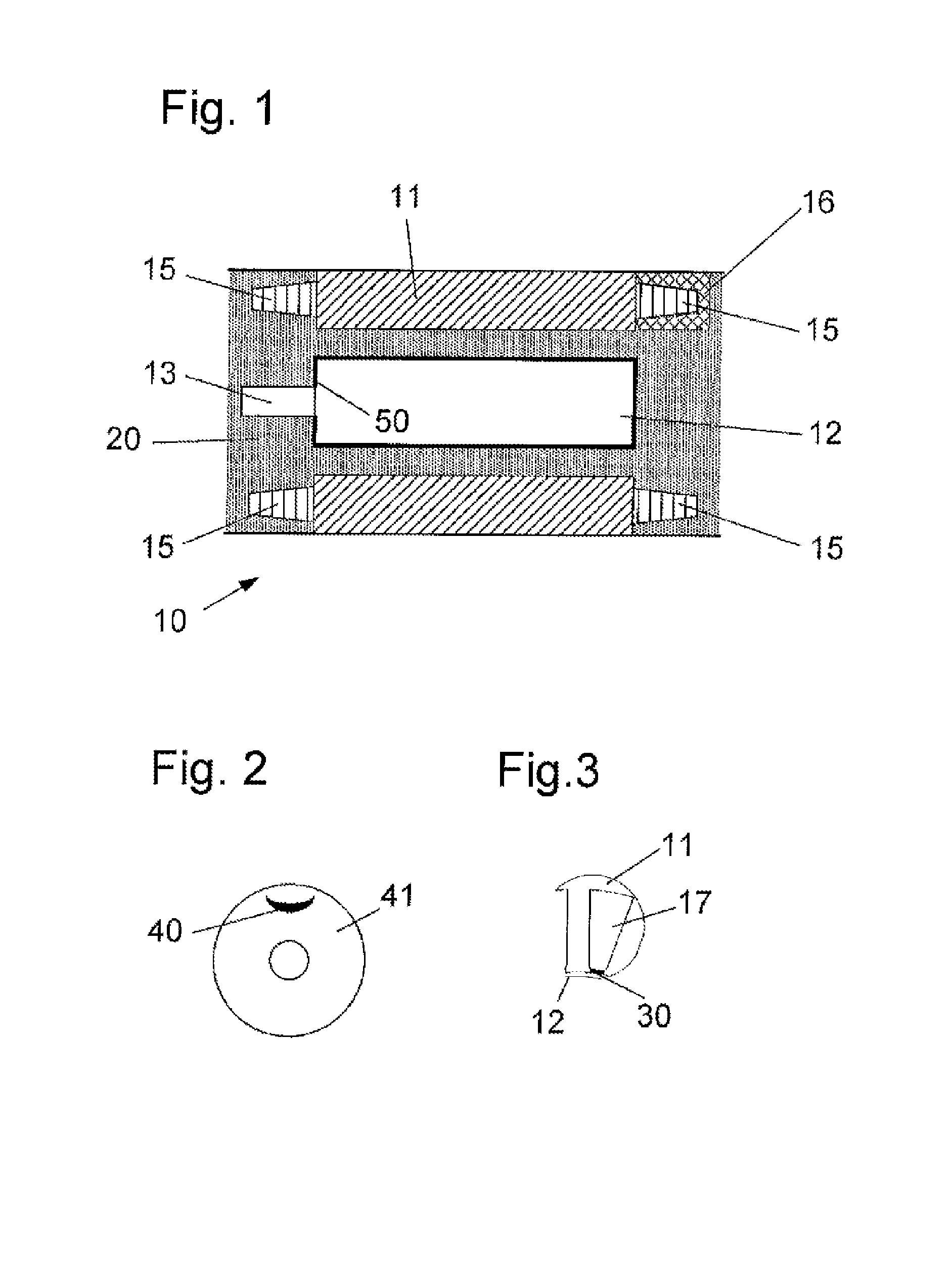
[0037]The synchronous reluctance motor 10 illustrated in FIG. 1 has a conventional stator 11 and a rotor 12 which is mounted rotatably with respect to the stator 11 and which is itself arranged coaxially on the shaft 13. The rotor body is composed of a laminated bundle, for example a lamination bundle, the individual layers or laminations being stacked in the axial direction of the shaft 13. A schematic illustration of an individual layer may be gathered from FIG. 2.

[0038]The clearance between the rotor wall and stator wall is designated as an airgap. According to the embodiment of the invention in FIG. 1, the motor inner space is filled with a ferrofluid 20, with the result that permeability in the region between the stator 11 and rotor 12 is increased and the comparatively large geometric clearance is compensated. The interaction between rotor 12 and stator 11, that is to say the reluctance force, is enhanced due to the increased permeability.

[0039]The ferrofluid 20 used is compos...


PUM


Abstract

The present invention relates to a synchronous reluctance motor for an underwater pump having a stator and a rotor which comprises a fluid barrier section for fanning one or more magnetic pole pairs, wherein the airgap between the rotor (12) and the stator (II) is at least partially filled with a ferrofluid (20). A further partial aspect of the invention relates to an underwater pump with such a synchronous reluctance motor for driving the pump.

Description

[0001]This application is National Stage of PCT International Application No. PCT / EP2013 / 057002, filed Apr. 3, 2013, which claims priority under 35 U.S.C. §119 from German Patent Application No. 10 2012 205 567.3, filed Apr. 4, 2012, the entire disclosures of which are herein expressly incorporated by reference.BACKGROUND AND SUMMARY OF THE INVENTION[0002]The invention relates to a synchronous reluctance motor for driving an underwater pump, having a stator / rotor arrangement, the rotor comprising a flow barrier cut for forming one or more magnetic pole pairs. The invention relates, moreover, to an underwater pump having a drive motor of this type.[0003]Underwater motor pumps serve for the conveyance of liquid media in boreholes. The housing outside of the motors is wetted completely or partially by the conveyed medium, usually groundwater. The pump drive motors used are of encapsulated form so as to prevent the conveyed medium from penetrating into the motor inner space.[0004]The mo...

Claims


Application Information

Patent Timeline
IPC IPC(8): H02K5/132F04D13/08
CPCH02K5/132H02K2201/03F04D13/08H02K1/02H02K1/06H02K1/22H02K3/42H02K5/12H02K5/1677H02K7/09H02K2213/03
Inventor URSCHEL, SVEN
Owner KSB AG
Why Eureka
Try Eureka