Current applying apparatus, current applying method and direct resistance heating apparatus

Active Publication Date: 2015-06-18
NETUREN CO LTD
View PDF35 Cites 5 Cited by
  • Summary
  • Abstract
  • Description
  • Claims
  • Application Information

AI Technical Summary

Benefits of technology

The present invention provides a current applying apparatus, method and direct resistance heating apparatus. The apparatus can easily apply a large current to a specific region of a workpiece through a simple and compact design. Additionally, the apparatus can change the current-applying region or time with a simple movement of the moving electrode, without the need for additional electrodes, power feeding structures, or complicated workpiece or bus bar designs. Overall, the present invention provides a more efficient and flexible solution for applying current to a workpiece.

Problems solved by technology

However, a heating furnace requires large-scale equipment, and a temperature control of the furnace is difficult.
However, to heat a workpiece such as a steel blank having small resistance by direct resistance heating, large current needs to be applied to the workpiece.
In this case, it is not easy to apply a desired current to the workpiece.
Further, when a plurality of pairs of electrodes is provided like in the second related art, an amount of electric current to be applied is controlled for each of the pairs of electrodes, which makes the apparatus complicated and large-scale.

Method used


Image

  • Current applying apparatus, current applying method and direct resistance heating apparatus
  • Current applying apparatus, current applying method and direct resistance heating apparatus
  • Current applying apparatus, current applying method and direct resistance heating apparatus

Examples


first embodiment

MODIFICATION OF FIRST EMBODIMENT

[0083]Although an example of using one electrode of the pair of electrodes 13 as the moving electrode 11 has been described in the first embodiment, both electrodes of the pair of electrodes 13 may be configured as the moving electrodes 11, 11, as shown in FIG. 4. In this case, the bus bars 25, 25 are separately provided so as to correspond to the moving range of both electrodes 11, 11 and respectively configure the current applying apparatus 20 as described above. Then, the heating target region is heated by moving both electrodes 11, 11 in a direction away from each other from the adjacent position in a state where voltage is applied between both bus bars 25, 25. Also in this current applying apparatus, the same operational effects as those described above can be obtained.

ANOTHER MODIFICATION OF FIRST EMBODIMENT

[0084]FIG. 5 shows another modification of the first embodiment.

[0085]In the first embodiment, the power feeding roller 41 is mounted on the...

second embodiment

MODIFICATION OF SECOND EMBODIMENT

[0125]Although an example of using one electrode of the pair of electrodes 13 as the moving electrode 11 has been described in the second embodiment, both electrodes of the pair of electrodes 13 may be configured as the moving electrodes 11, 11, as shown in FIG. 9. In this case, the bus bars 25 and the electrically-conductive brushes 45 are separately provided so as to correspond to the moving range of both electrodes 11, 11 and respectively configure the current applying apparatus 20 as described above. Then, the heating target region is heated by moving both electrodes 11, 11 in a direction away from each other from the adjacent position in a state where voltage is applied between both bus bars 25. Also in this current applying apparatus 20, the same operational effects as those described above can be obtained.

THIRD EMBODIMENT

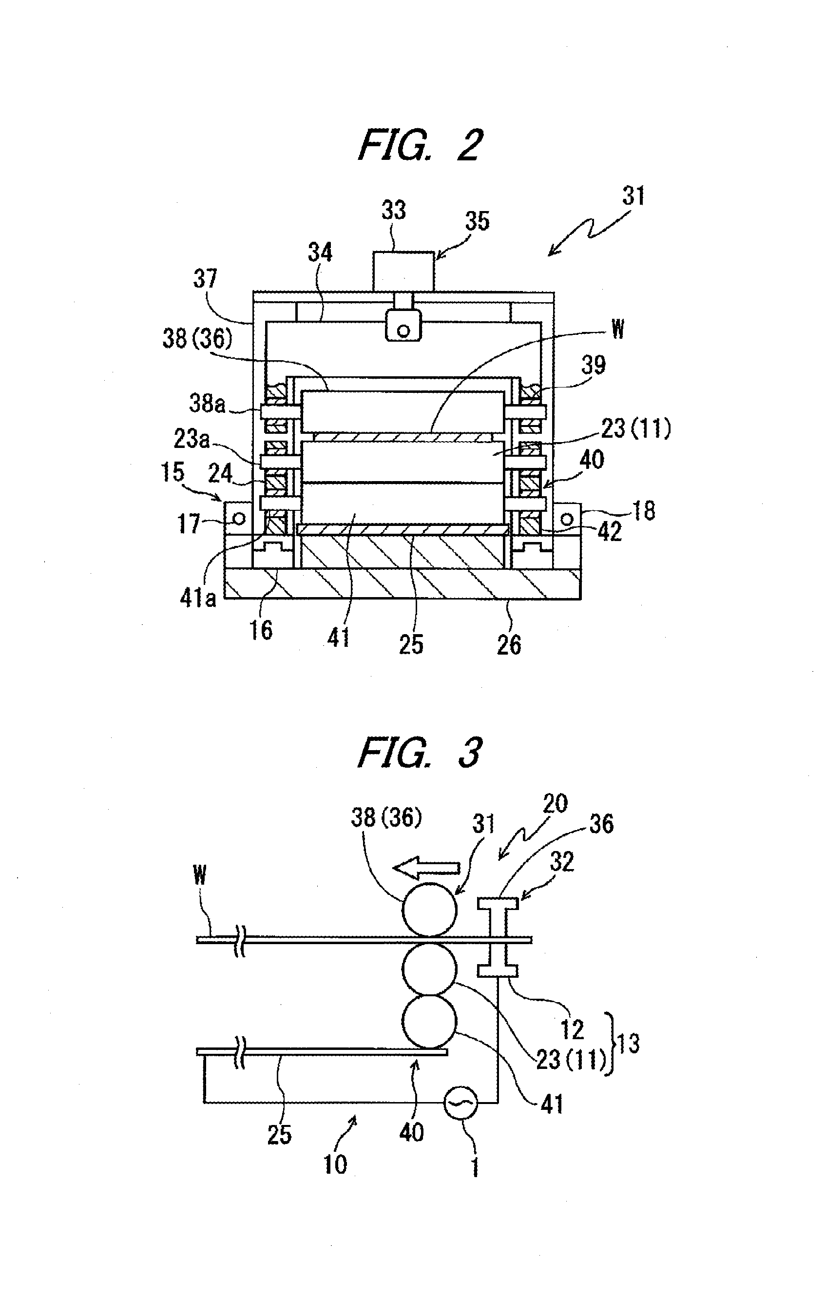
[0126]As shown in FIG. 10 and FIG. 11, the direct resistance heating apparatus 10 of the third embodiment includes the power...

third embodiment

MODIFICATION OF THIRD EMBODIMENT

[0159]Although one electrode of the pair of electrodes 13 has been used as the moving electrode 11 in the third embodiment, both electrodes of the pair of electrodes 13 may be configured as the moving electrodes 11, 11, as shown in FIG. 12. In this case, the bus bars 25, 25 are separately provided so as to correspond to the moving range of both electrodes 11, 11 and respectively configure the current applying apparatus 20 as described above. Then, the heating target region is heated by moving both electrodes 11, 11 in a direction away from each other from the adjacent position in a state where voltage is applied between both bus bars 25, 25. Also in this current applying apparatus 20, the same operational effects as those described above can be obtained.

[0160]Further, although the current-applying roller 23 and the power feeding roller 41 are mounted on the same shaft in the third embodiment, the current-applying roller 23 and the power feeding roller...


PUM

PropertyMeasurementUnit
Lengthaaaaaaaaaa
Currentaaaaaaaaaa
Electrical conductoraaaaaaaaaa

Abstract

A current applying apparatus includes a pair of electrodes configured to contact a workpiece to apply an electric current to the workpiece, and a bus bar arranged to extend along the workpiece. At least one of the electrodes includes a moving electrode configured to move relative to the bus bar and the workpiece such that an electric current flows between the bus bar and the workpiece through the moving electrode, the moving electrode being connected to the bus bar so as to be movable relative to the bus bar, and the moving electrode being configured to contact the workpiece so as to be movable relative to the workpiece.

Description

TECHNICAL FIELD[0001]The present invention relates to a current applying apparatus, a current applying method and a direct resistance heating apparatus, which are for directly applying an electric current to a workpiece such as a steel blank.BACKGROUND ART[0002]Heat treatment is applied to, for example, vehicle structures such as a center pillar and a reinforcement to ensure strength. Heat treatment can be classified into two types, namely, indirect heating and direct heating. An example of indirect heating is a furnace heating in which a workpiece is placed inside a furnace and the temperature of the furnace is controlled to heat the workpiece. Examples of direct heating include induction heating in which an eddy current is applied to a workpiece to heat the workpiece, and a direct resistance heating (also called as a direct electric conduction heating) in which an electric current is applied directly to a workpiece to heat the workpiece.[0003]According to a first related art, a me...

Claims


Application Information

Patent Timeline
IPC IPC(8): H05B3/03H05B3/02
CPCH05B3/023H05B3/03C21D1/40C21D9/0012C21D9/0068C21D9/46H05B3/0004H05B3/0009
Inventor OOYAMA, HIRONORIKOBAYASHI, KUNIHIRO
Owner NETUREN CO LTD
Why Eureka
Try Eureka