System and methods for engine air path condensation management

Inactive Publication Date: 2015-06-25
FORD GLOBAL TECH LLC
View PDF24 Cites 13 Cited by
  • Summary
  • Abstract
  • Description
  • Claims
  • Application Information

AI Technical Summary

Benefits of technology

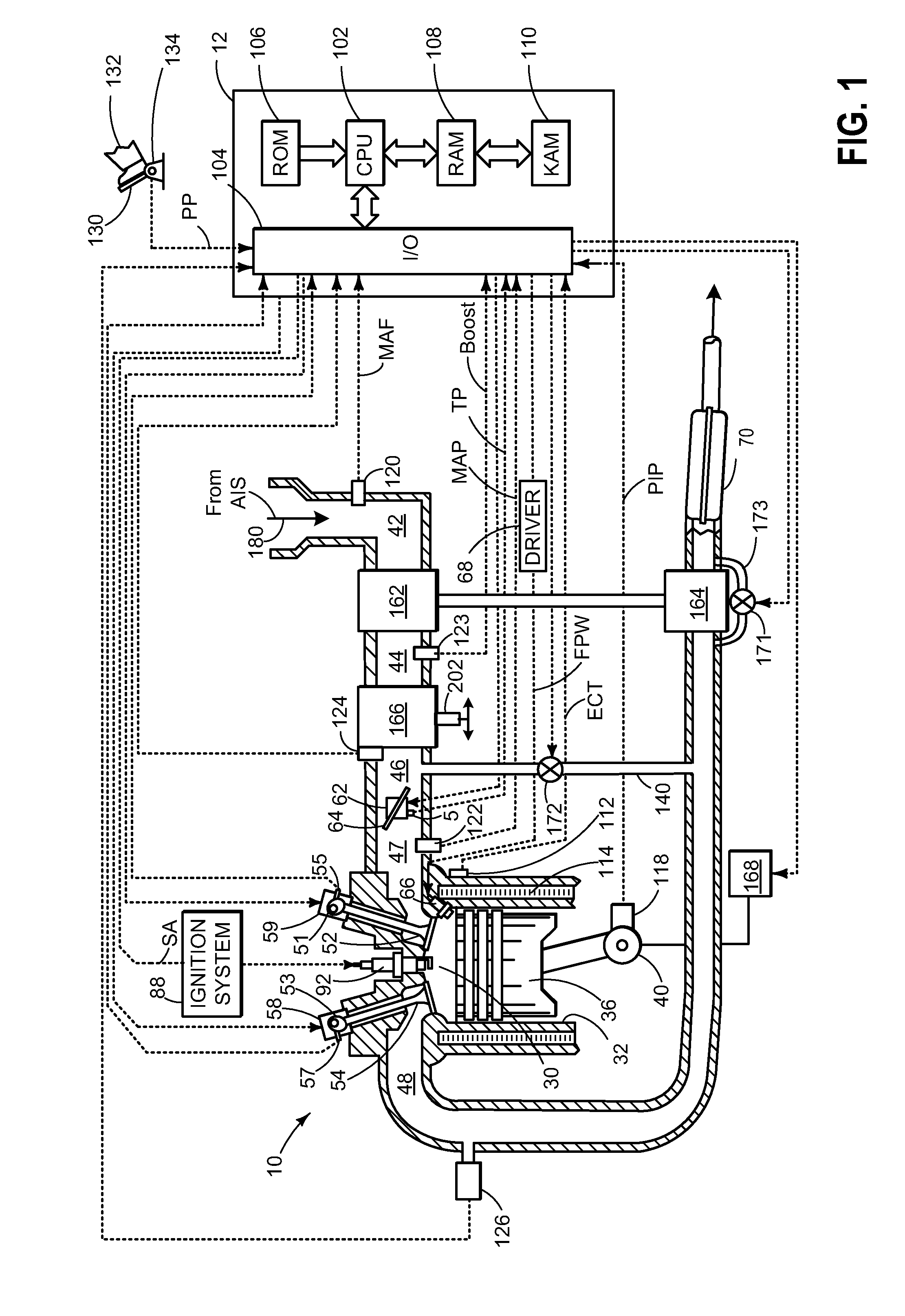
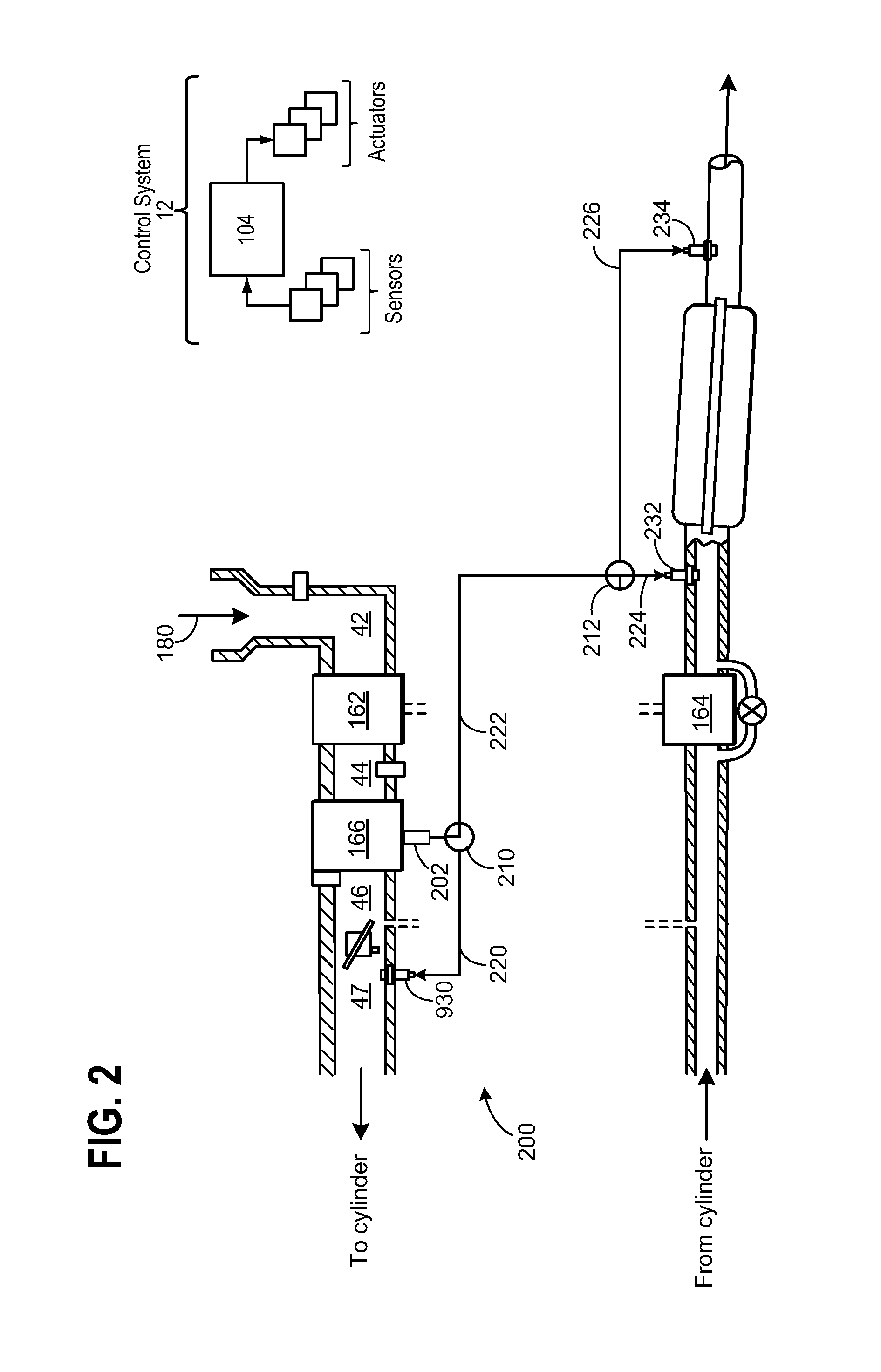
[0002]Boosted engines are in common use in which air is compressed by an air compressor powered by either a turbo positioned in the engine exhaust or powered by the engine crankshaft. Compression will increase air temperature. Consequently the compressed air is often routed through a heat exchanger commonly referred to as a charge air cooler before entering the engine air intake system. Under high ambient air humidity conditions condensate will form in the heat exchanger. In some prior approaches condensate is always routed into the engine exhaust and in other prior approaches condensate is always routed into the engine air intake.
[0003]The inventors herein have recognized that always routing the condensate to either the exhaust or the air intake regardless of engine operating conditions and regardless of whether there are contaminants in the condensate has led to undesirable engine or catalyst operation. For example, always routing condensate to the air intake system may result in rough engine operation under some operating conditions. And always routing condensate to the exhaust upstream of a catalyst at low or moderate engine loads may result in undesired catalyst cooling. Further, if engine oil is present in the condensate routing the condensate to the catalyst may result in undesired catalyst operation. Further, throwing away the engine oil by dumping it into the engine exhaust downstream of the catalyst is undesirable from an emissions or efficiency perspective.
[0004]The inventors herein have solved these issues by a method, in one example, which comprises: routing air from a compressor through a heat exchanger to a

Problems solved by technology

The inventors herein have recognized that always routing the condensate to either the exhaust or the air intake regardless of engine operating conditions and regardless of whether there are contaminants in the condensate has led to undesirable engine or catalyst operation.
For example, always routing condensate to the air intake system may result in rough engine operation under some operating conditions.
And always routing condensate to the exhaust upstream of a catalyst at low or

Method used


Image

  • System and methods for engine air path condensation management
  • System and methods for engine air path condensation management
  • System and methods for engine air path condensation management

Examples


Example

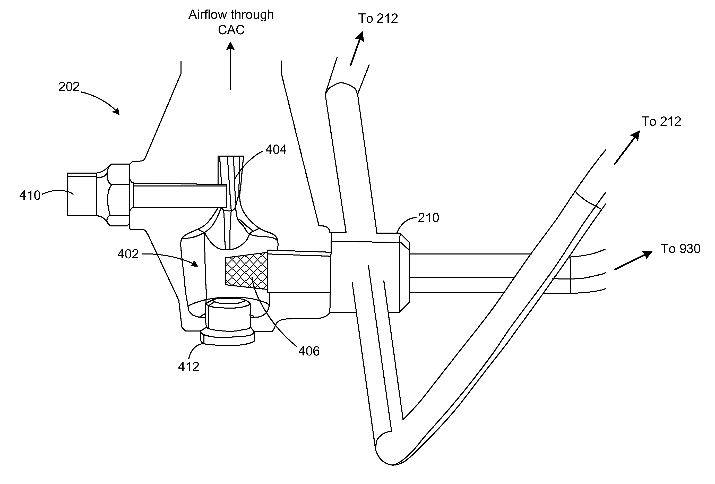
[0065]Turning to the second embodiment, FIGS. 9-14 show engine 10 including an auxiliary canister for storing pressurized air to aid in the routing of condensate under low engine operating conditions. In addition, the second embodiment further includes a passageway for directing condensate to each combustion chamber of the engine. As such, in some embodiments, the air routed into said combustion chambers may be further routed into an air intake system comprising: an air intake coupled to an intake manifold which is coupled to one or more intake runners each of which is coupled to one of the combustion chambers. The method further includes wherein the accumulated air is coupled through the passage only when the condensate is present and the engine output is below a predetermined amount. Briefly, controller 12 may disable airflow from the accumulator through the passageways when the engine output is above the predetermined amount. However, the second embodiment is described with respe...

Example

[0081]FIGS. 15 and 16 show a third embodiment for routing collected condensate to engine 10. In the third embodiment, an inline engine is shown wherein the lowest point in the intake system resides in intake manifold 47 rather than beneath CAC 166 as described above. This is because engine 10 according to the third embodiment includes an air to water heat exchanger as opposed to an air to air heat exchanger as described above for the V-engine configuration having an air to air heat exchanger (e.g., CAC 166). As described herein, in this engine configuration, which is illustrated with respect to an inline engine, condensate does not collect within the heat exchanger as described above. In addition, substantially no pressure differential forms across the heat exchanger because the air to water heat exchanger has a reduced size compared to CAC 166. Thus, routing collected condensate to various locations within the engine system presents additional distribution challenges that are solve...


PUM


Abstract

A system and methods for routing condensate collected in a heat exchanger reservoir to either a combustion chamber of an engine or a position in the engine exhaust based on the type of contaminate in the condensate and operating parameters of the engine or the catalyst are described. In one particular example, the method includes accumulating a portion of compressed air in an accumulator, and when an engine output is below a predetermined amount, coupling a part of the accumulated air with the condensate through a passage into the combustion chamber. Thereby, the methods described may be used to distribute condensate formed in the heat exchanger even at low engine loads.

Description

FIELD[0001]The field of the disclosure relates to detection of contaminants in condensate, formed naturally, and collected in a Charge Air Cooler coupled to an engine intake air path and / or exhaust air path whereby actions are taken in response to the detection.BACKGROUND AND SUMMARY[0002]Boosted engines are in common use in which air is compressed by an air compressor powered by either a turbo positioned in the engine exhaust or powered by the engine crankshaft. Compression will increase air temperature. Consequently the compressed air is often routed through a heat exchanger commonly referred to as a charge air cooler before entering the engine air intake system. Under high ambient air humidity conditions condensate will form in the heat exchanger. In some prior approaches condensate is always routed into the engine exhaust and in other prior approaches condensate is always routed into the engine air intake.[0003]The inventors herein have recognized that always routing the condens...

Claims


Application Information

Patent Timeline
IPC IPC(8): F02B33/44
CPCF02B33/44F01N3/04F01N3/2046F01P11/14F02B29/0468F02D2041/227F02M25/028F02D41/0025Y02T10/12
Inventor MACERONI, KAREN ELIZABETHMADIN, MARK MICHAELWICKS, CHRISTOPHER DONALD
Owner FORD GLOBAL TECH LLC
Why Eureka
Try Eureka