
Systems and methods for retrofitting existing lighting systems

a technology of lighting system and retrofitting method, which is applied in the direction of fixed installation, lighting and heating apparatus, lighting support devices, etc., can solve the problems of wasting energy, affecting the optimal distribution of light emitted from individual leds, and affecting the efficiency of lighting system, so as to achieve low electrical power consumption, improve efficiency, and reduce power consumption

Active Publication Date: 2015-06-25
AMERLUX
View PDF14 Cites 44 Cited by
  • Summary
  • Abstract
  • Description
  • Claims
  • Application Information

AI Technical Summary

Benefits of technology

This patent describes a method to protect LED lights from damage by using a sealant to encapsulate the light fixture. The sealant can be applied to the outer edge of the heat sink and inner edge of the optic lens, creating a strong and permanent seal. This method helps to maintain the brightness and durability of the LED lights. Additionally, the patent discusses the use of a high voltage Power Factor Correction (PFC) driver to increase the efficiency of the LEDs and reduce power consumption. The LEDs are connected in a series network to further reduce power consumption during standby mode. The patent also mentions the use of a surge protector to protect against lightning damage to the lighting system.

Problems solved by technology

Conventional roadway type light fixtures distribute light by using individual bubble type optics over individual LEDs with one optic per LED device, which inhibits optimal distribution of light emitted from the individual LEDs.
Because the omniscient directional light bulbs illuminate upwardly, less light is directed to pathways surrounding the street lights, creating light pollution and wasting energy.

Method used


Image

  • Systems and methods for retrofitting existing lighting systems
  • Systems and methods for retrofitting existing lighting systems
  • Systems and methods for retrofitting existing lighting systems

Examples


Embodiment Construction

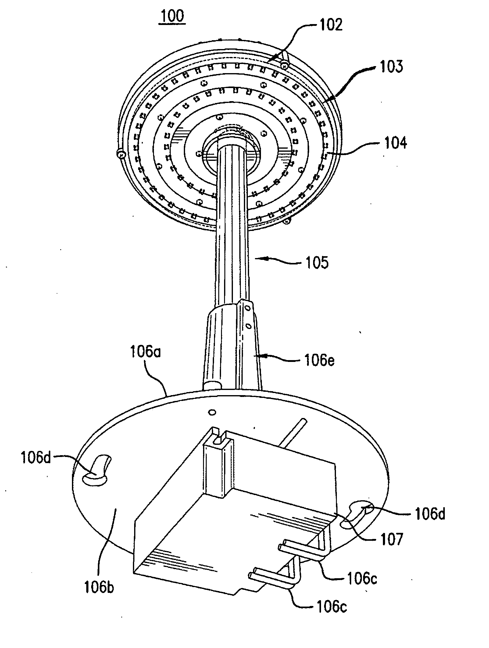
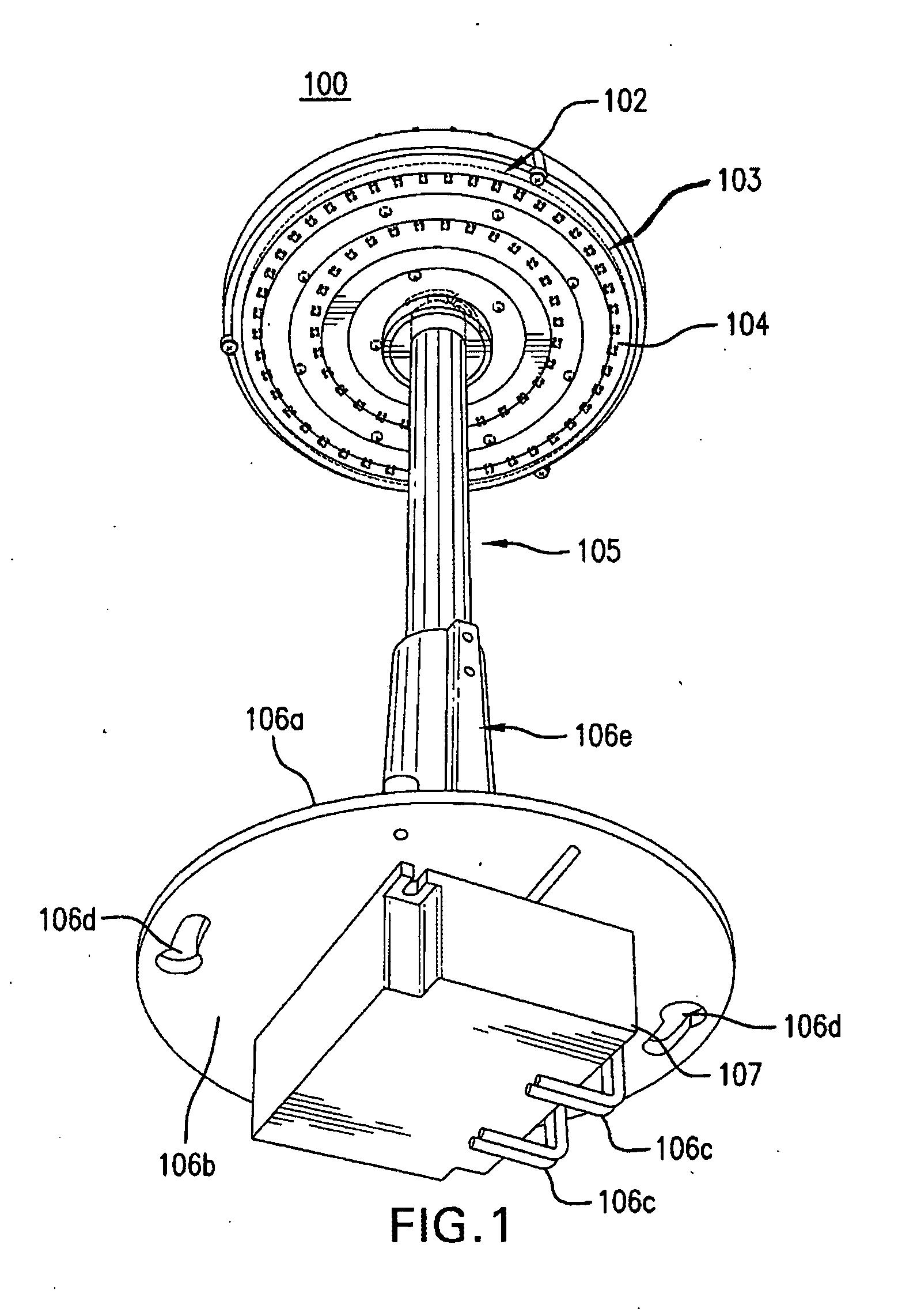
[0031]For purpose of explanation and illustration, and not limitation, an exemplary embodiment of the retro-fit lighting system is shown in FIG. 1, and is designated generally by reference number 100. This exemplary embodiment is also depicted in FIGS. 2-12.

[0032]Generally, as illustrated in FIG. 1, a retro-fit LED slighting device 100 of the present disclosure includes a retro-fit assembly 101 which includes an aluminum heat sink 102, a LED board 103, an optically active sealing lens 104, and an aluminum riser pipe 105. Alternative embodiments or variations of retro-fit device 100 can further include an adaptor casting 106 and an LED driver 107, as shown in FIG. 1.

[0033]In a preferred embodiment, the aluminum heat sink 102 is a circular plate with a raised annular edge 608 on one side of the plate, as illustrated in FIG. 12, sealed with a complementary circular LED board 103 and circular optically active sealing lens 104 encapsulated along the concentric outer ring of heat sink 102...


PUM

PropertyMeasurementUnit
currentaaaaaaaaaa
electrical currentaaaaaaaaaa
voltageaaaaaaaaaa

Abstract

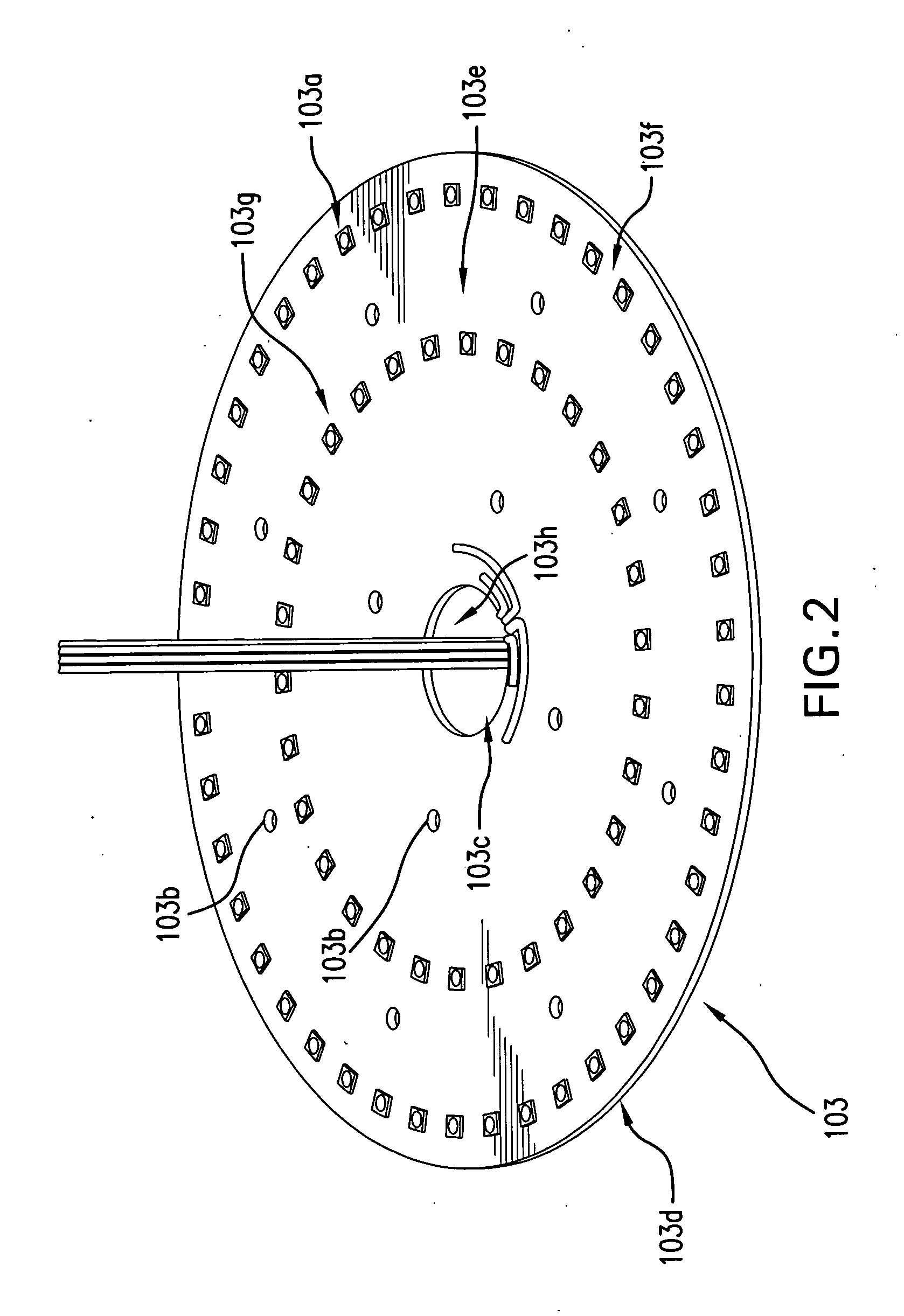
LED lighting systems and methods for retro-fitting existing lighting systems such as acorn and other globe style fixtures is disclosed. The retro-fit systems can be provided with an LED driver, an adaptor casting which mounts to industry standard fixture, a riser for adjusting the height of the lighting fixture, and an assembly of an optically active sealing lens, a heat sink and a LED board, wherein the LED lights, which can be made up of a plurality of LEDs, are arranged in concentric rings on the LED board, and are fitted with a sealing lens in the form of a rotated bubble optic with concentric grooves on the inner surface.

Description

FIELD[0001]The present disclosure relates to systems and methods for retrofitting existing lighting systems.BACKGROUND[0002]Lighting systems with acorn and other globe style fixtures are sometimes used for downtown or boardwalk areas. Typically, these street lighting systems are constructed with the fixtures sitting on top of omniscient directional light bulbs, protecting the bulbs from weather elements, such as lightning or rain. Conventional roadway type light fixtures distribute light by using individual bubble type optics over individual LEDs with one optic per LED device, which inhibits optimal distribution of light emitted from the individual LEDs. Because the omniscient directional light bulbs illuminate upwardly, less light is directed to pathways surrounding the street lights, creating light pollution and wasting energy.SUMMARY OF THE DISCLOSURE[0003]LED lighting systems and methods for retro-fitting existing lighting systems, such as those with acorn and other globe style ...

Claims


Application Information

Patent Timeline
Patent Type & Authority Applications(United States)
IPC IPC(8): F21V21/14H05B33/10F21V5/04F21V29/77H05B33/08F21K99/00H05B44/00
CPCF21V21/14H05B33/0887H05B33/0809F21Y2101/02F21V5/045F21V29/77H05B33/10F21K9/30F21S8/063F21V21/03F21V29/777F21K9/20F21Y2115/10Y10T29/49117F21V5/007F21V5/08F21V5/04H05B47/28H05B47/25F21S8/06F21S8/043F21V21/02F21S8/04
Inventor LESHNIAK, ITAIPOPPENHEIMER, TORI
Owner AMERLUX
Learn More