Self-cleaning optical sensor

a self-cleaning, optical sensor technology, applied in the direction of cleaning using liquids, fluorescence/phosphorescence, instruments, etc., can solve the problems of optical sensors not being able to optically analyze fluids, reducing or fully blocking light transmission,

Active Publication Date: 2015-06-25
ECOLAB USA INC
View PDF4 Cites 3 Cited by
  • Summary
  • Abstract
  • Description
  • Claims
  • Application Information

AI Technical Summary

Benefits of technology

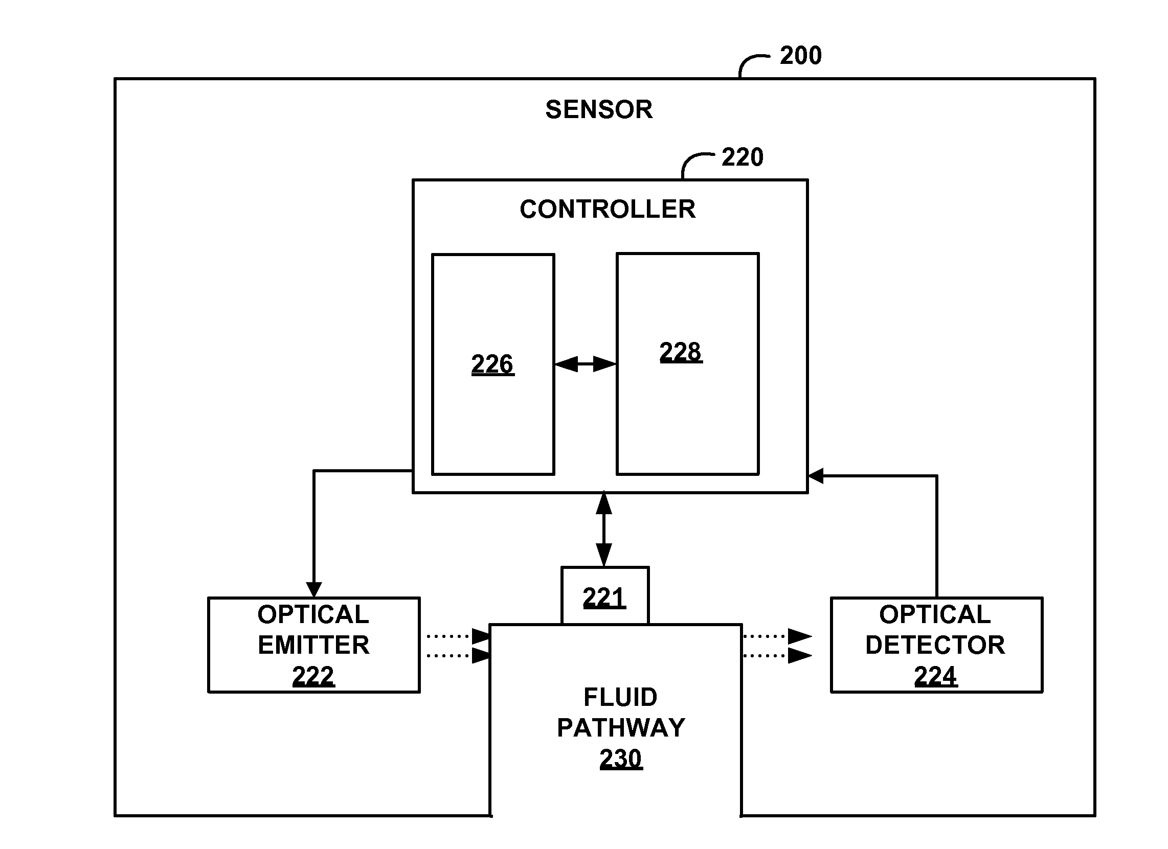
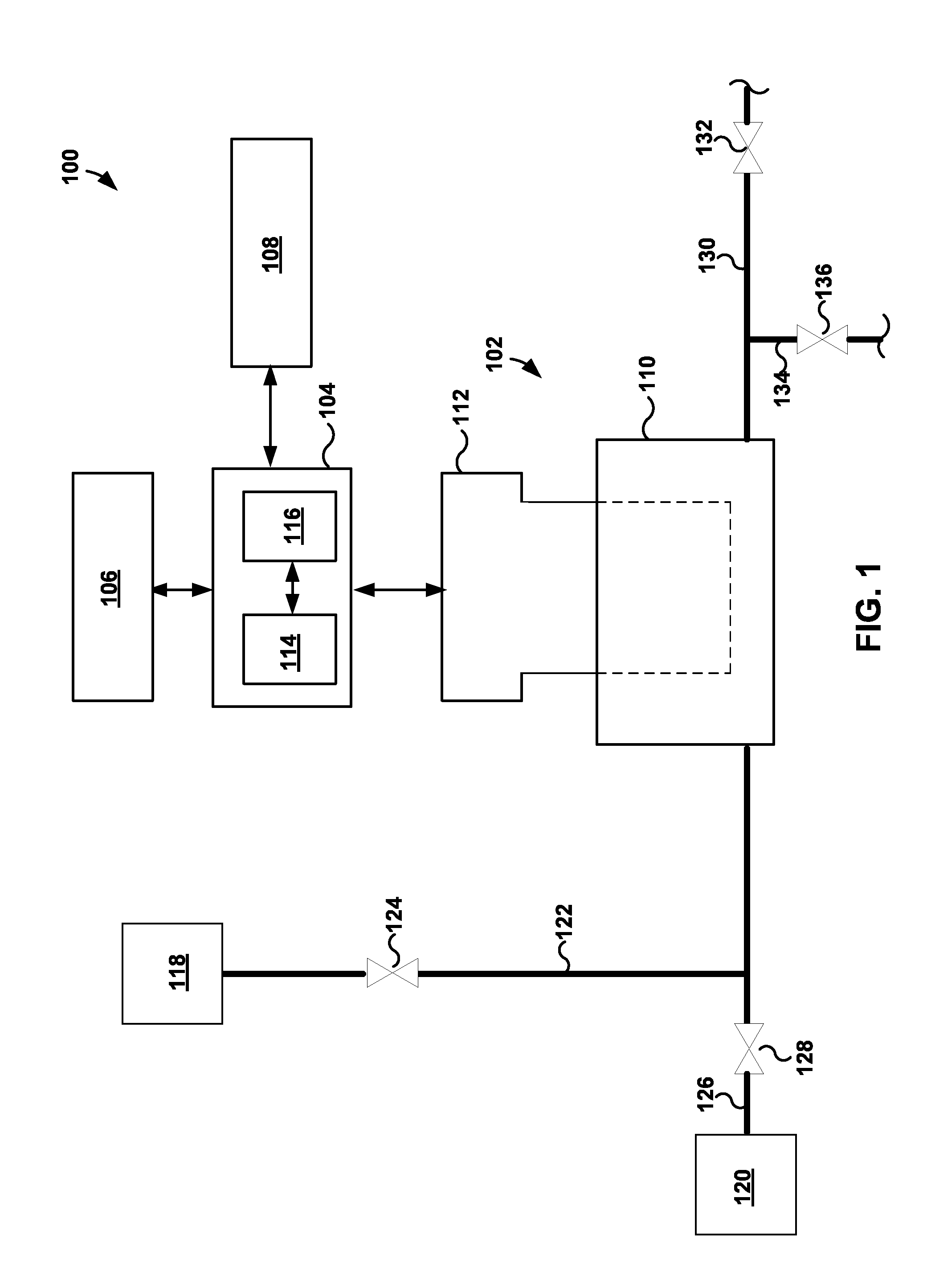
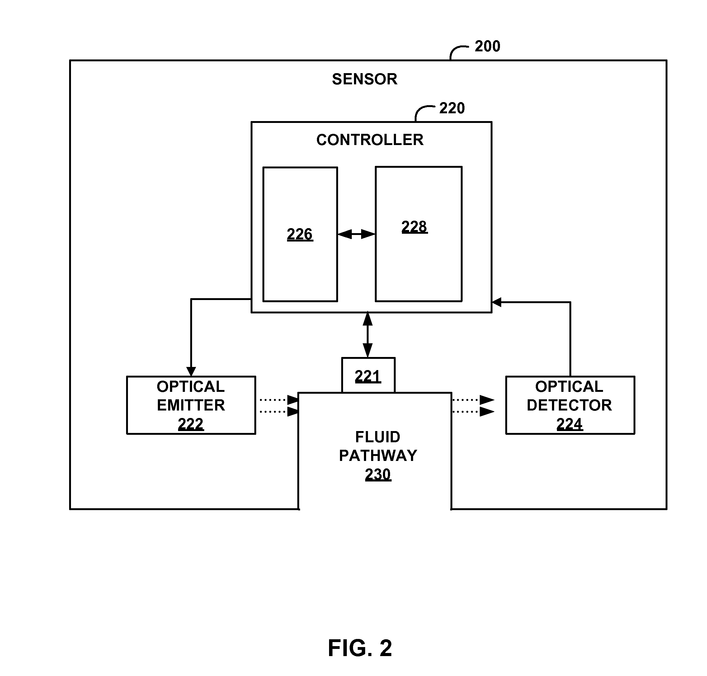
[0008]In some examples in accordance with this disclosure, a optical sensor is described that includes a flow chamber having an inlet port for receiving fluid for optical analysis by a sensor head. The inlet port may define a fluid nozzle that is configured to direct fluid entering the flow chamber against an optical window of the sensor head. In operation, fluid may travel through the inlet port and discharge from the fluid nozzle so as to impact the optical window of the sensor. The force of the incoming fluid impacting against the optical window may prevent fouling material from accumulating on the optical window and / or help remove accumulated fouling material from the optical window.

Problems solved by technology

If the fouling material accumulates within the optical sensor, the fouling material may reduce or fully block light from being transmitted to or received from the fluid by the optical sensor.
When this occurs, the optical sensor may not be able to optical analyze the fluid with the accuracy demanded by some applications.

Method used


Image

  • Self-cleaning optical sensor
  • Self-cleaning optical sensor
  • Self-cleaning optical sensor

Examples


Embodiment Construction

[0022]The following detailed description is exemplary in nature and is not intended to limit the scope, applicability, or configuration of the invention in any way. Rather, the following description provides some practical illustrations for implementing examples of the present invention. Examples of constructions, materials, dimensions, and manufacturing processes are provided for selected elements, and all other elements employ that which is known to those of ordinary skill in the field of the invention. Those skilled in the art will recognize that many of the noted examples have a variety of suitable alternatives.

[0023]Fluids with active chemical agents are used in a variety of different industries for a variety of different applications. For example, in the cleaning industry, fluid solutions that include chlorine or other active chemical agents are often used to clean and disinfect various surfaces and equipment. In these solutions, the concentration of the active chemical agent ...


PUM

PropertyMeasurementUnit
angleaaaaaaaaaa
wavelengthsaaaaaaaaaa

Abstract

An optical sensor may include a sensor head that has an optical window for directing light into a flow of fluid and / or receiving optical energy from the fluid. The optical sensor may also include a flow chamber that includes a housing defining a cavity into which the sensor head can be inserted. In some examples, the flow chamber includes an inlet port defining a flow nozzle that is configured to direct fluid entering the flow chamber against the optical window of the sensor head. In operation, the force of the incoming fluid impacting the optical window may prevent fouling materials from accumulating on the optical window.

Description

CROSS-REFERENCE[0001]This application is a divisional of U.S. patent application Ser. No. 13 / 464,508, filed May 4, 2012, the entire contents of which are incorporated herein by reference.TECHNICAL FIELD[0002]This disclosure relates to optical sensors and, more particularly, to optical sensor fluid control.BACKGROUND[0003]Aqueous chemical solutions are used in a variety of situations. For example, in different applications, aqueous cleaning solutions are used to clean, sanitize, and / or disinfect kitchens, bathrooms, schools, hospitals, factories, and other similar facilities. Aqueous cleaning solutions typically include one or more chemical species dissolved in water. The chemical species impart various functional properties to the water such as cleaning properties, antimicrobial activity, and the like. Measuring the concentration of the chemical species in the aqueous solution before use can be beneficial to understand the properties of the solution and to determine if adjustment is...

Claims


Application Information

Patent Timeline
Patent Type & Authority Applications(United States)
IPC IPC(8): G01N21/15G01N21/64G01N21/05
CPCG01N21/15G01N2021/6482G01N21/645G01N21/05B08B3/02B08B5/02G02B27/0006G01N2021/151G01N2021/6478G01N2201/0639G01N21/85G01N21/64
Inventor TOKHTUEV, EUGENEOWEN, CHRISTOPHER J.SKIRDA, ANATOLYCHRISTENSEN, WILLIAM M.
Owner ECOLAB USA INC
Why Eureka
Try Eureka