Stacked structure fur fuel cell

a fuel cell and stacked technology, applied in the field of stacked structure for fuel cells, can solve the problems of short-circuited single cells not being able to collect electricity in some cases, weakened defects such as bending or sagging, so as to improve the strength of stacked structures, prevent short-circuited interconnectors and frames, and increase the thickness of interconnectors.

Active Publication Date: 2015-06-25
MICO POWER LTD
View PDF3 Cites 2 Cited by
  • Summary
  • Abstract
  • Description
  • Claims
  • Application Information

AI Technical Summary

Benefits of technology

[0012]The present invention is directed to a stacked structure for a fuel cell capable of preventing interconnectors from being short-circuited while reinforcing strength in constituting a stack of a solid oxide fuel cell.
[0025]According to the above-mentioned stacked structure for the fuel cell, overall strength of a stacked structure is increased by additionally supporting side portions of the fuel cells through frames disposed in edge areas of the interconnectors, and thus occurrence of defects such as bending or sagging caused by heat or a load of the stacked structure during operation may be prevented without increasing a thickness of the interconnector.
[0026]Also, a complex functional part which is disposed between each interconnector and each frame and constantly maintains an gap interval therebetween is disposed, and thus short-circuiting of the interconnector and the frame may be prevented. Thus, as a result, since the short-circuiting of adjacent interconnectors is prevented, a fuel cell which does not connect electricity therebetween as mentioned in Discussion of Related Art is not generated, and thus electricity generated from all of the fuel cells may be efficiently collected.

Problems solved by technology

However, when the single cells and the interconnectors are manufactured to have very thin thicknesses so as to decrease a volume of the stacked structure, strength thereof is weakened, and thus defects such as bending or sagging may be generated by heat or a load during operation.
Also, when the bending or the sagging occurs as mentioned above, adjacent interconnectors may short-circuit in the extending space, and thus electricity generated from the short-circuited single cells may not be collected in some cases.

Method used


Image

  • Stacked structure fur fuel cell
  • Stacked structure fur fuel cell
  • Stacked structure fur fuel cell

Examples


Embodiment Construction

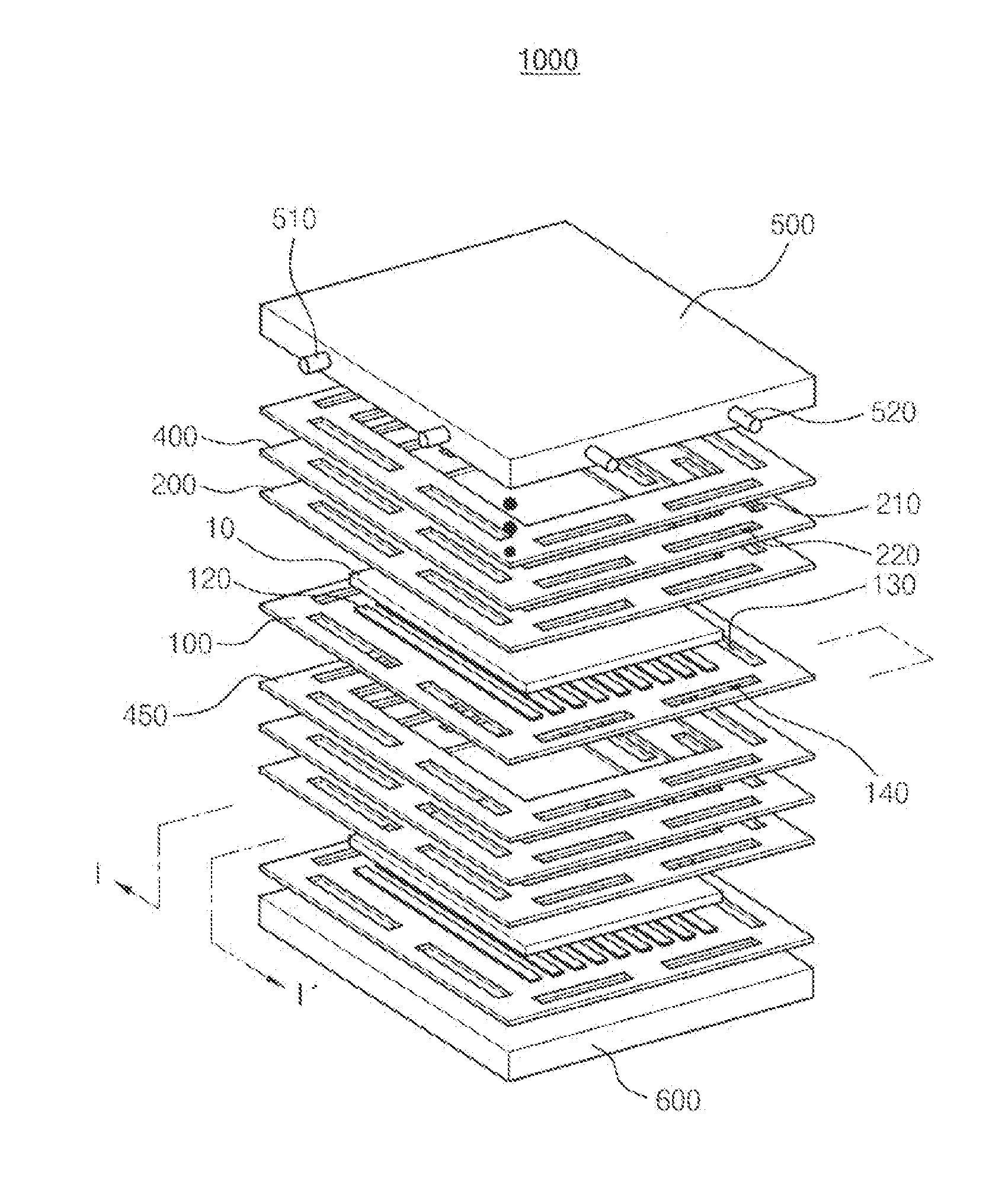
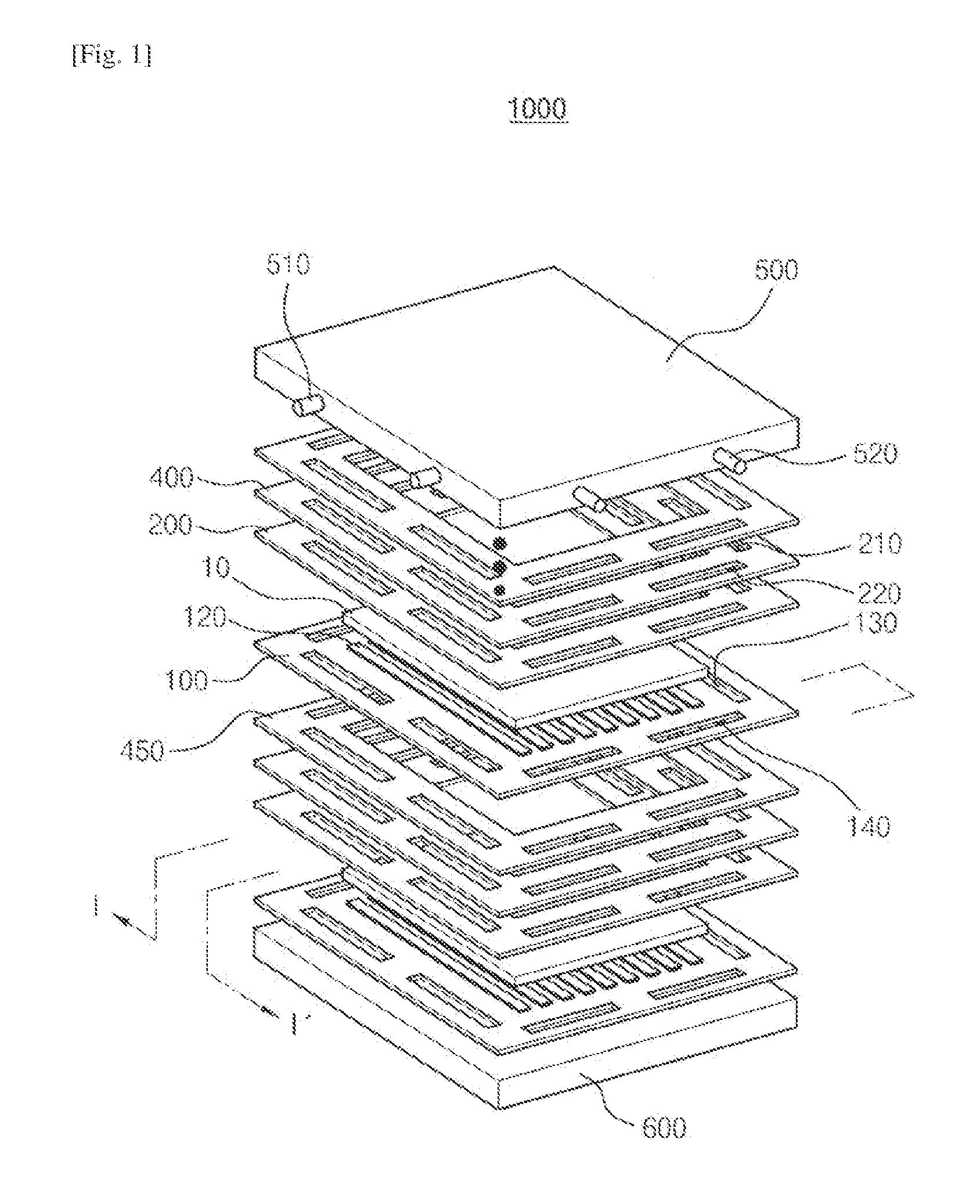
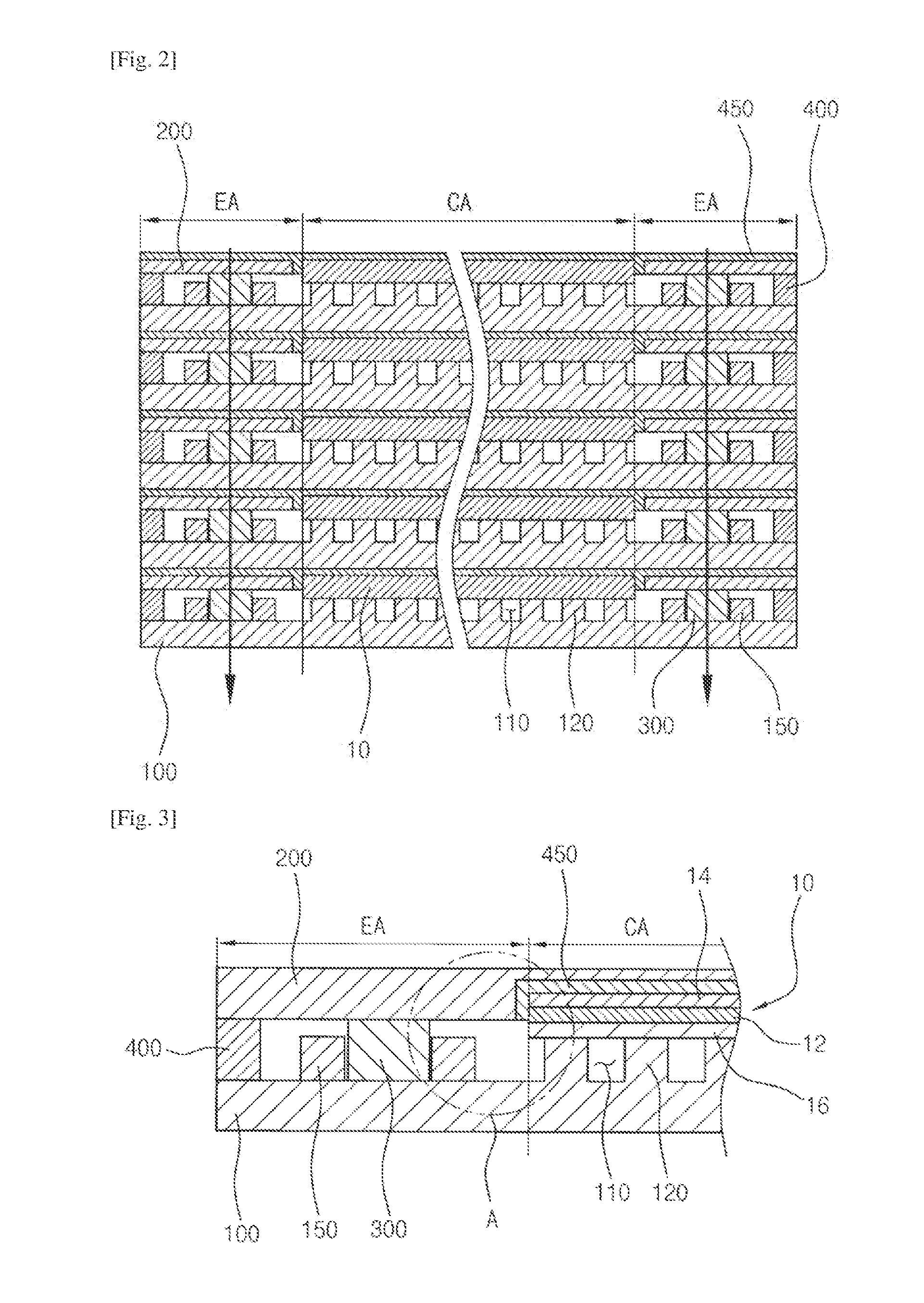
[0039]Exemplary embodiments of the present invention will be described in detail below with reference to the accompanying drawings. While the present invention is shown and described in connection with exemplary embodiments thereof, it will be apparent to those skilled in the art that various modifications can be made without departing from the spirit and scope of the invention.

[0040]In case it is mentioned that a certain component is “disposed” or “connected” on or to another component or layer, it may be understood that the certain component is directly disposed on or connected to the another component or that a component is interposed between the components. However, in case it is mentioned that a certain component is “directly” disposed or “connected” on or to another component, it should be understood that no component is interposed between the components. Though terms including ordinal numbers such as a “first”, a “second”, a “third”, etc. may be used to explain various compon...


PUM

PropertyMeasurementUnit
temperatureaaaaaaaaaa
voltageaaaaaaaaaa
thicknessaaaaaaaaaa

Abstract

Provided is a stacked structure for a fuel cell in which the plurality of fuel cells are stacked. Each of the fuel cells includes an electrolyte layer, and a cathode layer and an anode layer disposed on both surfaces of the electrolyte layer. The stacked structure includes at least one interconnector, at least one frame, and at least one complex functional part. The interconnector includes a central area electrically connected to the fuel cell, and edge area outwardly extending with respect to end portions of the fuel cell. The frame supports a side portion of the fuel cell to reinforce strength of the fuel cell supported by the interconnector. The complex functional part is disposed between the interconnector and the frame to constantly maintain an interval therebetween.

Description

CROSS-REFERENCE TO RELATED APPLICATION[0001]This application claims priority to and the benefit of Korean Patent Application No. 10-2012-0061316, filed on Jun. 8, 2012, the disclosure of which is incorporated herein by reference in its entirety.BACKGROUND[0002]1. Field of the Invention[0003]The present invention relates to a stacked structure for a fuel cell, and more particularly, to a stacked structure in which a plurality of fuel cells are stacked to increase an electric power amount.[0004]2. Discussion of Related Art[0005]Generally, fuel cells are power generators which include a cathode layer and a anode layer formed on both sides of an electrolytic layer, respectively, and in which, when air including oxygen and a fuel gas including hydrogen are caused to flow to the air electrode layer and the fuel electrode layer, respectively, the hydrogen reacts with the oxygen through an ion conductive phenomenon in the electrolytic layer, and thereby electricity is generated.[0006]The fu...

Claims


Application Information

Patent Timeline
Patent Type & Authority Applications(United States)
IPC IPC(8): H01M8/24H01M8/02
CPCH01M8/242H01M2008/1293H01M8/0273H01M8/0202H01M8/2432H01M8/2457H01M8/2483H01M8/2465Y02E60/50H01M8/02H01M8/12H01M8/24
Inventor CHOI, SONG HOPARK, SANG PILKIM, SUNG WOOK
Owner MICO POWER LTD
Why Eureka
Try Eureka