
Resonant energy harvester, aircraft component comprising the resonant energy harvester and an aircraft comprising the resonant energy harvester or the aircraft component

a technology of resonant energy harvester and aircraft component, which is applied in the direction of piezoelectric/electrostrictive/magnetostrictive device, kinetic-electric generator, piezoelectric/electrostrictive/magnetostriction machine, etc., can solve the problems of high voltage generation of charge collecting device, uncmos-compatibility, and harm to electric devices or communication systems. , to achieve the effect of high energy outpu

Active Publication Date: 2015-06-25
AIRBUS DEFENCE & SPACE
View PDF1 Cites 6 Cited by
  • Summary
  • Abstract
  • Description
  • Claims
  • Application Information

AI Technical Summary

Benefits of technology

The invention relates to a technology for generating energy from triboelectricity, which involves using a cantilever type structure to charge a conductive section instead of directly. The technology can be applied to aircraft components, such as the fuselage, and can generate energy from mechanical vibration. Compared to other methods, the technology ensures a high energy output and can be used in locations where there is no or too little mechanical vibration.

Problems solved by technology

An aircraft typically collects charges during cruising by air friction; these charges (which can be harmful for electric devices or communication systems) are being released by so-called static dischargers.
This may lead to the generation of high voltages at charge collecting device.
These materials are not CMOS-compatible and, hence, cannot be easily manufactured.
The vibration of the cantilever due to vibrational noise acting on the energy harvester may generate some additional energy, but as this energy is spread across a large bandwidth, only a small technical relevant amount of energy may be harvested.

Method used


Image

  • Resonant energy harvester, aircraft component comprising the resonant energy harvester and an aircraft comprising the resonant energy harvester or the aircraft component
  • Resonant energy harvester, aircraft component comprising the resonant energy harvester and an aircraft comprising the resonant energy harvester or the aircraft component
  • Resonant energy harvester, aircraft component comprising the resonant energy harvester and an aircraft comprising the resonant energy harvester or the aircraft component

Examples


Embodiment Construction

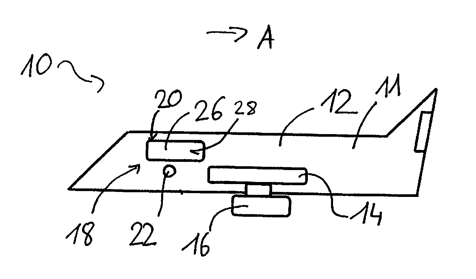
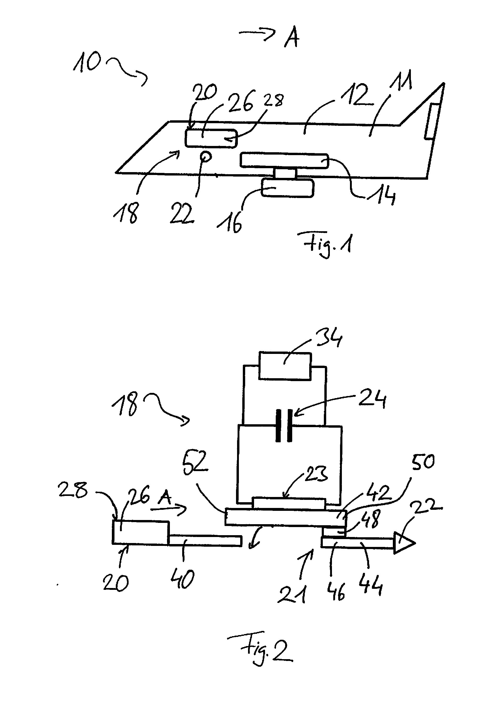
[0039]Initially referring to FIG. 1, an aircraft 10 is built up by aircraft components 11 such as a fuselage 12 and a wing 14. A jet engine 16 is mounted to the wing 14. An energy harvester 18 is also provided with the aircraft 10.

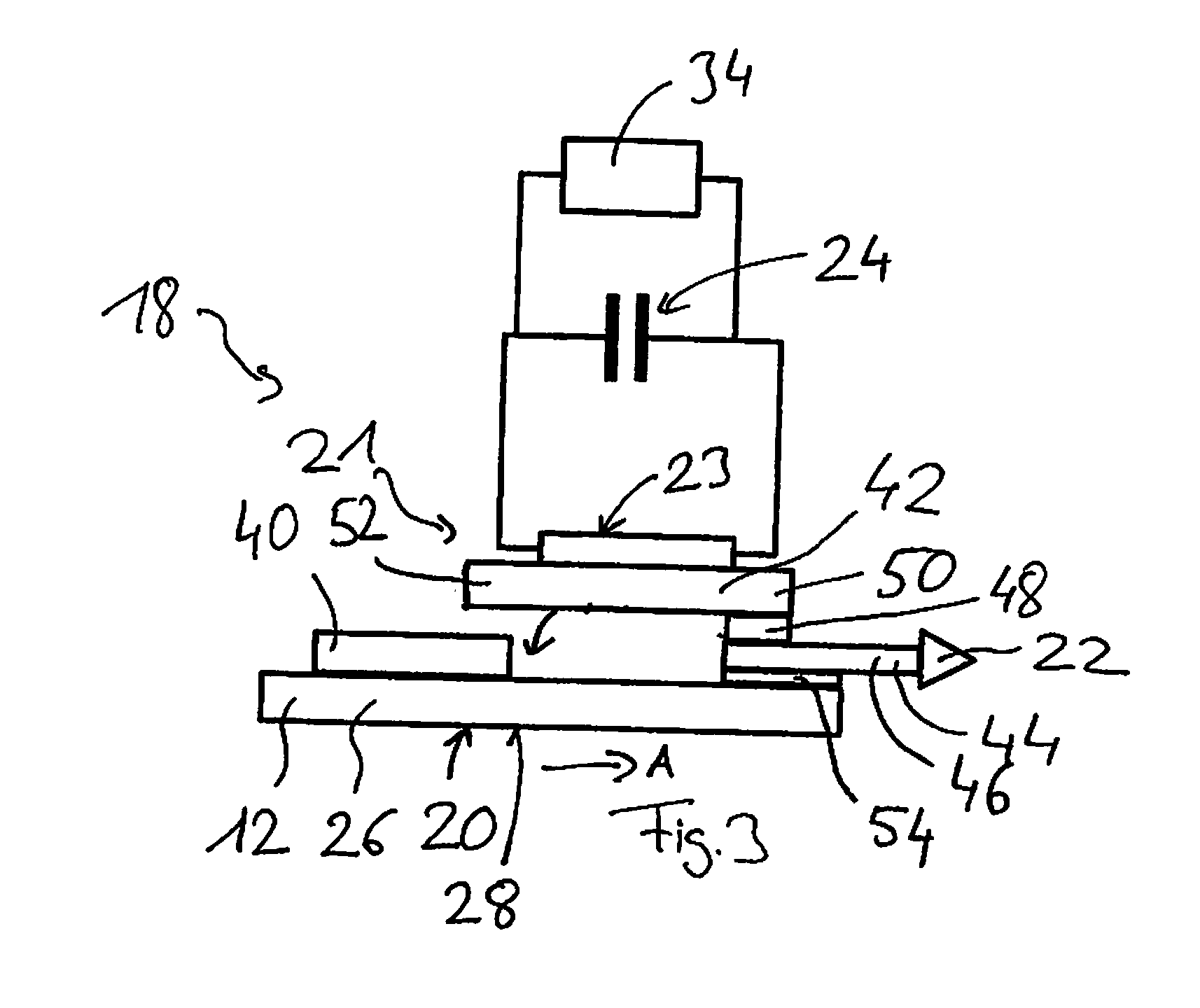
[0040]The energy harvester 18 has a first portion 20, a movable element 21, and a kinetic-to-electric-energy-converter 23. The first portion as a charge collecting device 26 and a first conductive section 40. The charge collecting device 26 is a plate-shaped member having a surface 28 that is exposed to an air flow A flowing by the aircraft 10. The first conductive section 40 is in electrical connection with the charge collecting device 26.

[0041]The movable element 21 has a second portion 22 and an elastic element 42. The second portion 22 is in electrical connection with a second conductive section 44 that electrically connects the second portion 22 with the elastic element 42. The second portion 22 is made of metal and has the shape of a cone. The second...


PUM


Abstract

An energy harvester for an aircraft comprises a first portion, a movable element and a kinetic-to-electric-energy-converter. The first portion includes a charge collecting device having an electrical permittivity different to that of air. The charge collecting device is configured to be exposed to an air flow. The movable element is configured to be driven by the charge of the charge collecting device, and the kinetic-to-electric-energy-converter is configured to generate energy by the movement of the movable element.

Description

CROSS-REFERENCE TO RELATED APPLICATION[0001]This application claims priority under 35 U.S.C. §119(a) to European Patent Application No. 13 199 094.7, filed on Dec. 20, 2013, the entire contents of European Patent Application No. 13 199 094.7 are hereby incorporated herein by reference.BACKGROUND[0002]1. Field of the Invention[0003]The invention relates to an energy harvester. Furthermore, the invention relates to an aircraft component comprising the energy harvester. The invention also relates to an aircraft comprising the energy harvester and / or the aircraft component as described before.[0004]2. Background Information[0005]Static electricity is a well-known effect of materials being in contact at first and then got released from each other. This effect can be enhanced by friction, called triboelectricity. A short description is given in Dominic Samson, Energy harvesting in aircraft with special focus on thermal electrics, Dissertation, TU Vienna, 2011:“If two bodies with different...

Claims


Application Information

Patent Timeline
Patent Type & Authority Applications(United States)
IPC IPC(8): H02N2/18H02N1/00H10N30/30
CPCH02N1/006H02N2/186H02N2/185H02N3/00H10N30/306
Inventor BECKER, THOMASELEFSINIOTIS, ALEXANDROSSCHMID, ULRICH
Owner AIRBUS DEFENCE & SPACE
Learn More